
![]()
Since this project has been getting long, I broke it into two pages. Part I is here.
Before I continue, in case you came here without having read other sections of this website: this isn't quite your standard restoration blog. I use this partly as my memory and I think aloud; I record my mistakes, stupid and otherwise; and I try to make it a little bit entertaining and not treat things like heart surgery.
Nov 26 - No! Not Another One
I didn't want to start anything big with Thanksgiving looming, but thought I'd poke around a little. So I'll start off this web page with a stupid mistake. I printed out the chart of operating voltages for all the tubes. Fired up the machine and, not getting the hum, started poking. I wrote down the voltages I was getting so I could compare them with what I should expect.
I'm not getting heater voltages. What gives? If I tap the wiper on the volume control I get noise. If I fiddle with the chassis the hum kicks in and rattles the workbench. And the dial lights are all on—they run off the same heater string.
I'm measuring against chassis ground, which is how it is according to the schematic. I've got the pins right.
Finally a call to The Old Man. What range are you using on your meter?
Oh....... The heaters run directly off AC.
That done, I thought I'd attack the remaining electrolytics, which might be the source of the hum. Looking around I'd found two electrolytics as discreet capacitors and convinced myself for a happy afternoon that they were singles; there was no can. Until I went looking for the high voltage jobs.
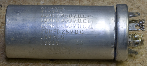
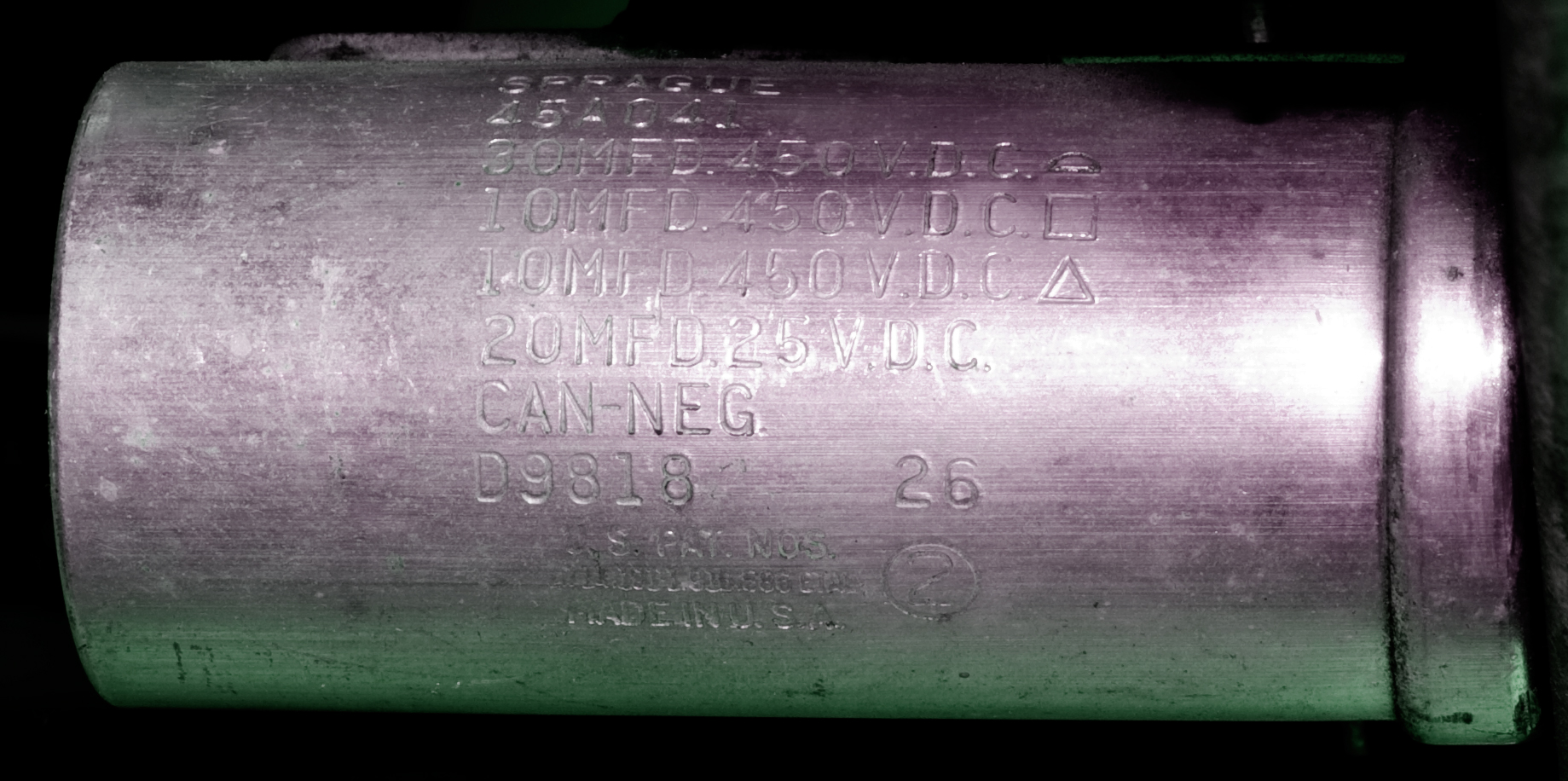 They're in a can. A four-stage can, though if I read it right, the two 10µF stages are run parallel to produce 20. Either way, ugh. This is what has derailed me on the Zenith. I had removed it and made a mess of documenting what-went-where, and now I'm paying for my sins trying to reconstruct it. Or actually, not reconstructing it, but setting it on the shelf so I could screw up this project in the meantime.
I hate electrolytic cans.
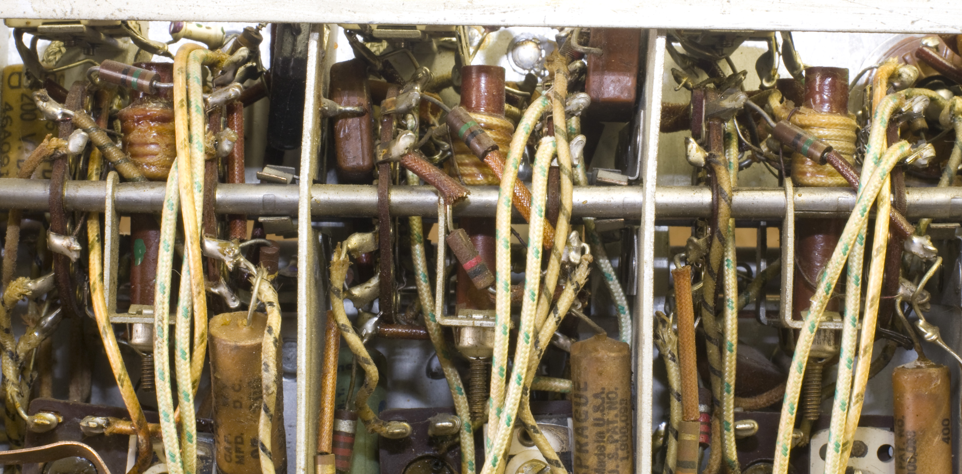
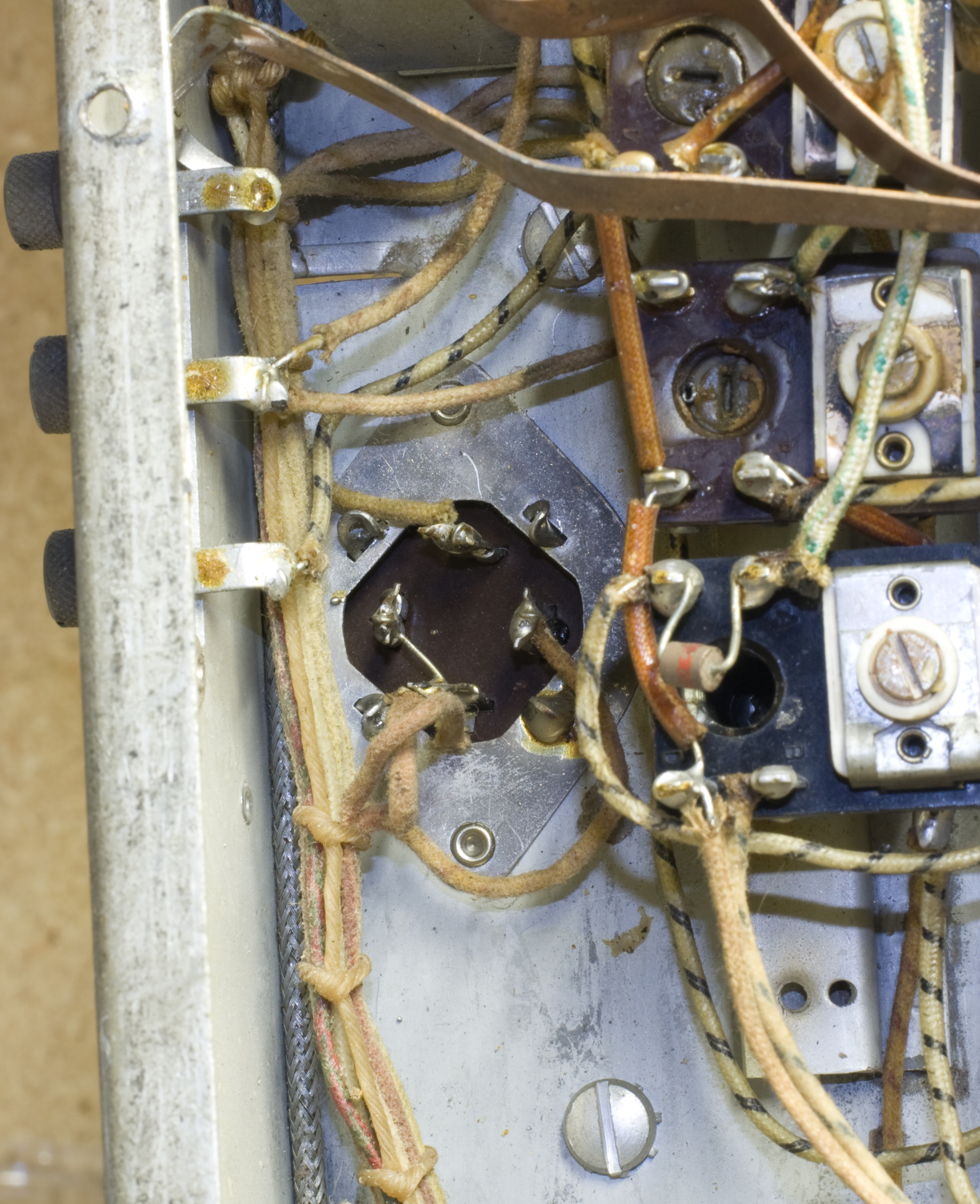 This time I took photos (click on them for larger images) to try and make it a little easier; and I'm going to figure a better way to identify the wires so I know which goes to what terminal. This isn't quite as simple as it would seem, because this beast is wired like an automobile and the wiring harnesses go all over hell. In this example, the can is in the back corner of the chassis over the antenna terminals, but the wires go up front to the audio output tubes, and then come back to the speaker terminals.
Some of these woven-cloth wires are marked but many look identical to me. My migrane is starting up already.
This time I took photos (click on them for larger images) to try and make it a little easier; and I'm going to figure a better way to identify the wires so I know which goes to what terminal. This isn't quite as simple as it would seem, because this beast is wired like an automobile and the wiring harnesses go all over hell. In this example, the can is in the back corner of the chassis over the antenna terminals, but the wires go up front to the audio output tubes, and then come back to the speaker terminals.
Some of these woven-cloth wires are marked but many look identical to me. My migrane is starting up already.
This one has two things in its favor over the Zenith: one is that there's more space and everything's easier to get to; the other is I don't have to disconnect eighteen things in the process. That's why I made the image so huge; hopefully it'll help me keep straight what's what.
[Later] I decided it may not be such a debacle afterall. One wire goes to the top terminal (top as oriented in the photograph to the left), one on the right-side terminal, two on the bottom, and none on the left-side. The bottom and left-side are shorted. Nothing's tied to the ground lugs outside. So I pulled the wires and tagged them, and wrote everything in my notebook. I can't do a lot more than that.
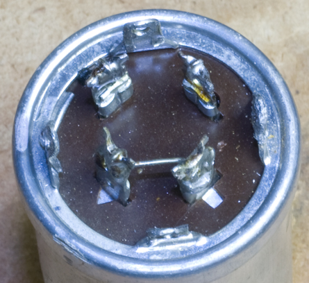 The other big thing was getting a good look at the can to see how the lugs are identified. I know there are symbols marked on the side of the can (a half-circle, a square, a triangle and "no symbol", but I couldn't see where they were marked on the lugs themselves. Once I got it out, I finally see it. They're cutouts on the insulation plate! In the photo to the right, the lug in the lower right corner has the square cut-out; the lower right has the triangle; the upper left has no cutout at all, and the upper right corner has the demi-circle. I took a look at the can for the Zenith and I see where they did the same thing. Wish I'd known that then.
December 6 - Opening the Can
I began by watching this video on YouTube, which was informative but ultimately didn't work for me. There were too many obstructions and there was just no way I was going to be able to pry the top up like that, so I ended up cutting the end with a Dremel.
Here's what it looked like inside. A little bit of tar (?) on the inside, but not nearly what I was bracing for. There's a rubber band holding the dielectric backing. Take that off, and it unwinds as a long roll of foil and cloth.
Each one of those straps is attached to a lug, and each strap was attached to the foil; the innermost one was attached, and then the foil/cloth was wound around it, and do on.
So this is where I am now. Ready to solder on the new caps. The only problem is that each of those straps is attached to a positive lug; I'll have to make one for the negative connection.
I didn't photograph the final product because it's not much to look at, but I did my best to solder the new caps in. Big problem turned out to be the material of the can and straps, which I can't solder to. I presume they're aluminum. I'm not so concerned with the positive leads because I twist them around the straps a couple times, but I tacked the ground lead onto the "base" and it has a tentative hold at best.
After that I wrapped it with electrician's tape to keep the positive straps from shorting against the can itself. That'll create parasitic capacitances but hopefully not enough to matter. I fit the can back on. I'm debating about how or whether to seal it shut. If I seal it, I'll probably get a more positive ground. If I leave it unsealed, it'll be a lot easier to open it up again if I need to.
So back in, hooked up. Check for shorts—negative. Wires connected the way I'd had them diagrammed? Affirmative. Fire it up. HUMMMMMMMM enough that I could see the speaker (face down) creaping across the workbench.
Various checks and things look okay. Try it again. No change.
Dec 8 - If You Don't Know What To Do
The old man can't hear if it's AC hum or something else over the telephone, as the sound quality is too degraded. He suggests patching a 10Ω resistor across the speaker terminals to cut the volume. That doesn't seem to make any difference. He'd suggested shorting the grid of the phase inverter, which is feeding the amplifier, on the theory that the hum could be coming from upstream; and that does nothing. I also try checking the filter can by patching each cap through a sub box that I have. That does nothing. I'm now slow, low and out of ideas.
If you don't know what to do...do something else. There are a couple of old wax .02 wax capacitors that are easy to swap out. They're physically on the back chassis next to the antenna terminals. Where they are on the schematic is anybody's guess. There are a bunch of .02s sprinkled throughout the system. They bypass something to ground.
So I swap them out, and for the hell of it, fire it up again and—quiet! Now I can hear what I think really is hum, but it's relatively soft. Did I get it?
Of course I get nothing else. Try tapping the wiper for the volume control—nothing. So now I've gone from ear-rattling audio to zilch.
If you don't know what to do...do something else. I'll put the front panel back on; I don't think there's anything more to do with the front other than break the frequency display discs. I gave the panel a final wash in soapy water, which appears to have done nothing but didn't hurt anything either: I'll take that.
Put the S-meter back in, and time to hook it up. I know how the wires go but the paper box is origami and makes no sense. Thank God I photographed it. You'd think. The photograph turned out to be helpful but not enough. Trying to get the meter hooked up again was impossible with the box in the way; it appears that its job is to keep the meter leads from shorting against the chassis; fine, they won't.
One of the flaps fell off, and I decided to Hell with it, and cut the rest off. Amazing how easy the meter is to hook up without that damn box tangling everything. It's back in, the wires are a mile away from the chassis; the bulb is in.
Face goes back on. The little bandspread window pops back on. Now the big one—wait, I need the big tuning knob. Where's the big tuning knob?
 It's MIA. I was going to clean it but haven't gotten to it yet. Now I need to try and clean it up, put it back on, then the big plastic dial cover goes on, and I can put the rest of the knobs on.
Can't find the tuning knob. It's not in the places it ought to be. It's not in the places I think it could be. It's not in the places it shouldn't be. The last I remember seeing it was when I photographed it. I know what I did—I put it somewhere safe where nothing would happen to it. But I can't remember where that is.
So—the end of another day. If you don't know what to do...do something else: which is why I'm typing this up.
Later
Found the knob. If you can't be melodramatic, what's the point of doing anything?
Cleaned up the knob, put it back on, put the others on. I haven't gotten the bandspread knob back on yet because I'm not entirely sure how it goes (and I didn't photograph it in detail)—in particular I'm not sure where the snap-ring goes. Also noticed that the bandspread dial and tuner-caps do not appear to turn when I turn the shaft, so everything may have to come off again; hopefully it won't come to that.
Still no audio.
Dec 11 - RTFM (Read the Manual)
Servicing the Audio Section for Hum. . . . One possible cause of hum is cathode-to-heater leakage in one of the audio tubes. Since the heater circuit is powered by the line, some 60-cycle current from this source can get into the cathode circuit through the leakage path. Here it enters the signal circuits of the audio chain, where it will be amplified and appear in the loudspeaker as hum. Another possibility is an open grid circuit. This defect has been mentioned before as a possible source of low volume and erratic reception. It also can cause a type of motorboat effect which is close to the hum frequency and may be mistaken for it.
When checking for hum, the servicing procedure is first to investigate the filter circuit and then, if this does not help, to replace the audio tubes one at a time, while listening for a reduction in the hum. If the hum still persists, the audio grid circuits are checked for an open. An easy way to do this is to bridge the grid-load resistors with a test resistor of approximately 1MΩ, while listening to the effect on the loudspeaker.
Practical Radio Servicing by Marcus & Levy, pp. 166-167
Read that this morning and thought I'd give it a try. Last night I tore apart the re-stuffed filter can and rewired the caps in directly. It ain't pretty and it won't last but it works and it absolutely elminated the filters as my problem (or at least made me feel better about it). I need to do a better job with the can anyway. I either need to find a better way to solder the negative leads to the shell or I'll have to drill a hole through the phenolic base and pass a negative lead out through it, and solder that to a ground lug.
So I swapped out the two 6V6 power out tubes (I know it said one-at-a-time) and plugged in two that test good. Still got the racket. The grid-load resistors, if I read the schematic right, are 220K each, and I was shocked to discover a couple of 220K resistors that were actually on the tube sockets, not located on the opposite end of the chassis connected up to six feet of wire via the harness. So I pulled out my resistor sub box, picked the 250K resistor, got ready to do the bridging without, hopefully, shorting something catastrophically, and the audio went out again.
This was beginning to remind me of the disaster that's been the Wards battery radio project, where I had chonically intermittant audio gremlins that I never could kill.
It seemed like this happened when I was poking around the resistors on the tube socket base. Maybe there was an intermittant short. There's a bunch of stuff that's tightly packed around there, so I prodded and finessed some leads and wires a bit just to make sure, and turned it on again.
No audio. Well, there's noise—is it just quiet? I tapped the wiper on the volume control. BOOM BOOM. Got it! I suspect I either had a short or a lead from something was too close to the filament pin on one of the output tubes.
Just for fun, I clipped a lead on the antenna and spun the dial across AM broadcast. Nothing. I fired up the signal generator, set it for 1MHz, clipped it up to the antenna lead and hunted. Nothing.
Last try. I set the generator for AF and poked the grid on the 6V6s. Beeeeeeeeeeeeep! Woo hoo! I've got audio.
Next up is to do the filter can up right, put it back on, and then I can start moving backward along the signal path.
Dec 13 - Another Wall
Despite being Friday the 13th, things are going well enough to be expected. I keep insisting on using the RCA signal generator, even though it's a pain-in-the-ass. I have to check it with the freq counter to make sure I'm really getting signal from it, because the push-in test lead connectors are worthless. Over Christmas I'm going to see if I (or more likely the Old Man) can convert it to BNC connectors.
I started signal tracing. Audio on the 6V6 outputs—fine. Audio on the grid of the Inverter—fine. IF on the plate of the 2nd IF tube—fine. IF on the plate of the 1st IF tube—fine. IF on the grid—fine. RF (1MHz) on the plate of the 2nd RF Amp tube—fine. RF on the grid—nothing.
Hmmmm.
 Poked around at different points but it seems clearly that the 2nd RF tube is breaking the chain. Swap it out with another 6AG5. No difference. Swap with the 1st RF tube (also a 6AG5). No difference. Got the Hickok out and tested four 6AG5s (two from the radio and two more from the shelf) and they all tested fine, and more-or-less the same.
Now what? Not sure. Both RF stages are on top of and obscured by the band switches and various trimmers, so space is particularly tight. I had a hell of a time even touching the grid on the 2nd RF tube, so I'm not 100% sure I got it (but I'm 99% sure). I am sure that I get sound when I touch the plate on the 2nd RF tube.
 So at the moment I'm scratching my head until I can figure out what to do. I've already got the side-access panel off. The next level of disassembly appears to be taking apart the structure that holds the band switches, and I want to do that like I want to take out my own appendix.
Damn miniature tubes. I wish they'd stuck with octals. (Yes, I know...)
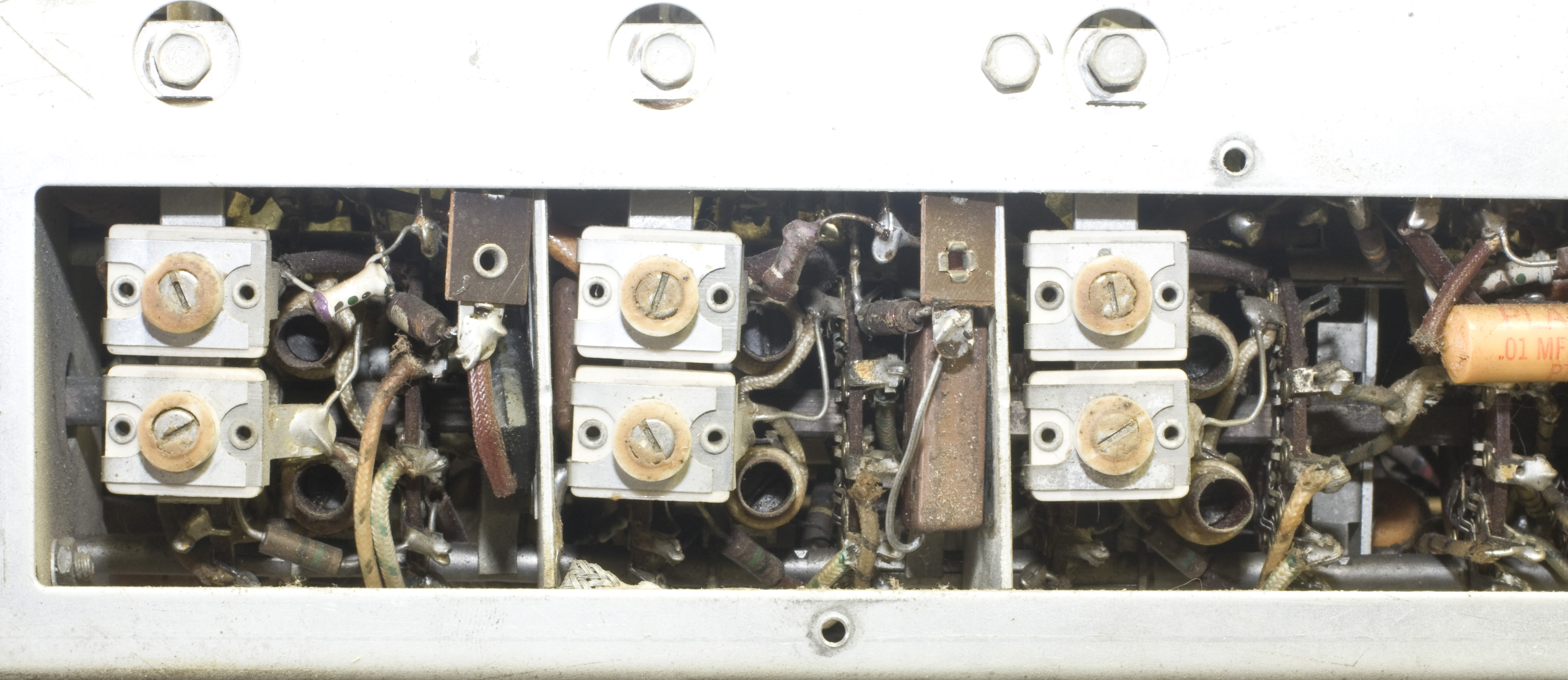
Photos above to show people what I'm up against. The upper photo is where the radio is stood up on its side, RF secton on top (power transformer and audio section are on the bottom). You can't even see the tube socket. The lower photo is the same section but the radio is sitting properly, and we're looking the side, with the access pane removed. The tubes are located to the right of those hex-head screws. Again, you can't even see the tube sockets.
For a brief moment I was hoping the problem was an exposed resistor lead that may be shorting against the chassis, (upper photo middle) but no such.
Dec 13 - Be Positive
At the beginning of this thing (in Part I) there's a list of websites where people have restored SX-42s; but of those only Phil Nelson has a detailed, blow-by-blow account, so I skimmed it again to see if he mentioned having to work in the RF section, and indeed he did. In particular, this bit caught my eye:
Equipped with three different versions of the schematic, I got to know the SX-42's circuitry, especially its bandswitch, very well. In the course of removing the repairman's temporary hotwiring, I also uncovered further problems, each of which had to be remedied before proceeding further.
The most prominent bit of hotwiring was a jumper wire connecting the B+ voltage supply of the first RF amplifier tube to the B+ supply of the second RF tube. (Both tubes are type 6AG5, by the way.)
When I simply removed that jumper, the radio went dead on BC. Testing the voltage on the second RF tube quickly showed the reason. No B+ voltage was being supplied.
-- This Concludes the Good News Portion of Our Program
I decided to check voltages. I still can't get to all the pins but I can do a few. A few minutes later I had my answer: no B+ on the plate of the 2nd RF tube. I have proper (within reason) voltages on the 1st RF and the Mixer on either side, so it's just the 2nd RF tube. No B+ on the plate and nothing on the screen grid (if I tagged the right one).
On the one hand, I'm pleased that I figured this out somewhat on my own, and it explains why the tube is lit but still not working. The other hand is that the B+ chain is broken somewhere, and that is Bad. Phil's problem was a bad wafer switch, and the thought of that makes me ache all over.
I decided to go for a Hail Mary play: I physically unplugged the machine, drenched all the switches with contact cleaner, in particular the 2nd RF wafer, and spun the band switch a bunch of times to "clean" it. Now I'm letting it dry thoroughly so I don't blow up something else by causing a short because of there's a pool of chemicals somewhere. Later on I'll know that it doesn't work, but at least I'll have tried.
Later: It didn't work.
Dec 14 - If You Don't Know What to Do . . .
. . . replace paper capacitors. According to the Operating Instructions manual, which has a parts list, there are 44 by my count. I'd already replaced a bunch on the back (audio) end, there were some 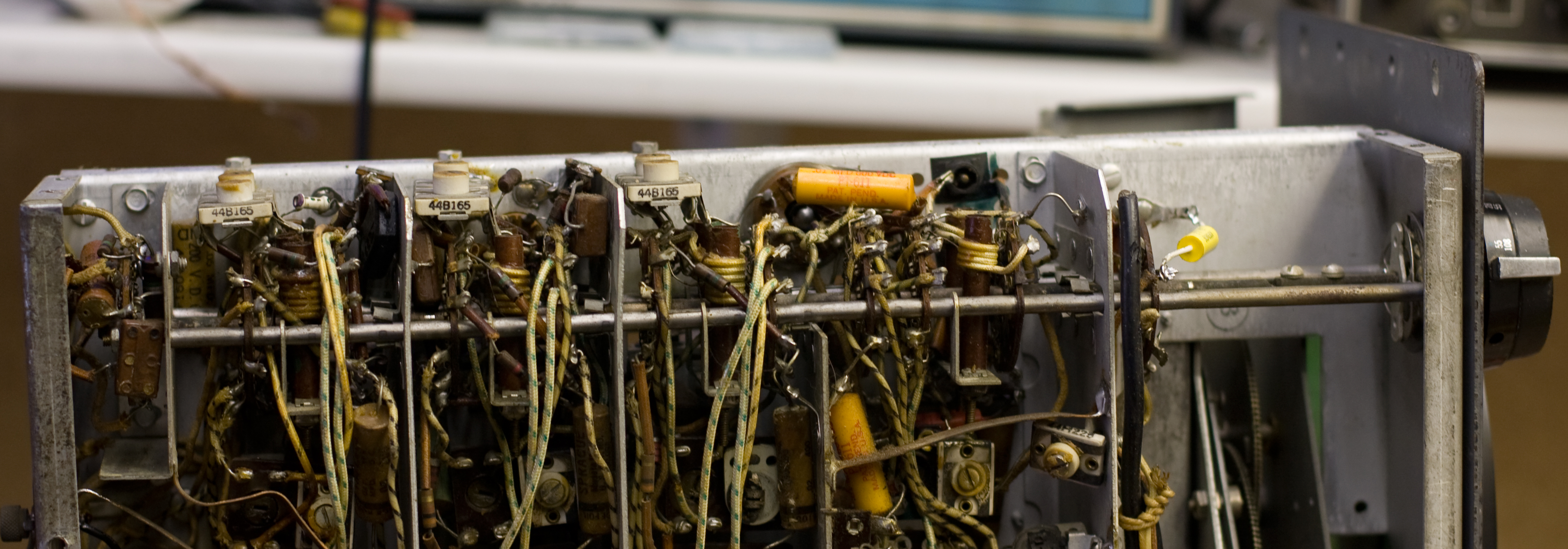 others that had been done by The Old Man, but there were still several dozen left to do. I replaced the easy ones, then the not so easy ones. Then I took the side bracket off, which exposed some more. Now I'm down to five that I can see but can't get to. There are a couple more things I may be able to remove to expose them, but I'll have to be extra careful because I don't want to damage the trimmers.
Here's the photo with the side bar off. It's easy to remove: two screws on the front panel and several hex-heads on the panel itself. It makes it a bit easier to get to the tube sockets, but it's still tight.
Dec 15 - Back to the Filter Cap
I'd had the filter capacitors bodged in while I was troubleshooting; since I'm now stalled, I decided to attempt to build the can again. After much cursing, solder smoke, the making and breaking of connections, I'm going to try a different tack.
The problem is still that I can't solder to the internal strips, which I assume are aluminum or some other metal that doesn't play well with solder. I'd already given up on the idea of grounding it, so I bored a hole through the phenolic base to run a ground wire through and solder to the outer lug. In the meantime, one of the internal strips broke off at the base, so I bored a wire through that so I could solder to the lug. I still tried to hard-wiring on the other three, but it's a disaster and looks like a tinker-toy project built by a man wearing boxing gloves. So screw it: I'm going to cut all the internal strips off flush, bore holes through the base, and run the leads through and solder to the outer lugs. Purists who are offended can kiss it.
Dec 21 - Filter Cap In
Finally got the filter cap back in, with help from a Dremel tool to open up the slots a little bit. Put the cap in, checked for shorts, wired everything up, and fired up the radio make sure. Runs quiet now, no hum. Audio still good. Still no B+ on the 2nd RF tube.
Dec 22 - No Greetings from El Jefe This Year
Not on this set, anyway. I'll probably fire up the National tonight and see if I can get Snoopy's Christmas again.
I may tinker a little more and see if I can for-sure determine that the wafer switch really is where I'm losing B+, rather than an open resistor or broken wire somewhere else. Not sure how I'll do it, but I'll try.
Regardless, to anyone who reads this: Merry Christmas for American-culture English speakers; Happy Christmas for Brit-culture English speakers; Feliz Navidad for Españolophones, Joyeux Noël, Buone Feste Natalizie, Mele Kalikimaka, Chung Mung Giang Sinh, and for everyone else you can look it up here.
Feb 8, 2014 - In the Doldrums
I haven't written anything lately because there's nothing to write about. I lost momentum completely during the Christmas-New Years holidays and haven't been able to get thing moving again.
The problem is that I'm just stuck. I have no B+ and I can't trace the problem because everything's buried. I haven't figured out a way to partially disassemble bits to gain access in the area. I did try to remove one of the trimmer-cap sets that are mounted on a bar that goes into the chassis; doing that would expose a wire I wanted to probe for continuity. For my trouble all I did was break the corner off a nearby coilform, and I still couldn't probe it because the wire appears to be cloth-covered.
I'm still poking, but it looks like I'm going to have to bleat for help from The Old Man. And I can bet this won't be the kind of problem he'll enjoy solving, either.
Feb 16 - So I Rewired It . . .
.jpg) If you stand the radio up on its side with the power transformer at the bottom (it would be bottom-left corner) and look at the under-chassis, where all the caps and resistors and wiring are, there's a bus that runs horizontally almost in the exact middle of the chassis, just above the two 7H7 limiter tubes. The bus is connected up to part of the wiring harness and feeds power here there and everywhere.
If you stand the radio up on its side with the power transformer at the bottom (it would be bottom-left corner) and look at the under-chassis, where all the caps and resistors and wiring are, there's a bus that runs horizontally almost in the exact middle of the chassis, just above the two 7H7 limiter tubes. The bus is connected up to part of the wiring harness and feeds power here there and everywhere.
Long story short: the Old Man traced it up and down, and finally determined that somewhere between the filter choke the bus, there must be an open. He suspects that when I was replacing caps, I may have accidentally nipped one of the wires, and we're not seeing the disconnect. As it's a jumble there, it's difficult to spot where it might be.
Since the wiring is done via a harness and is very difficult to trace, we finally decided to run a new wire from the choke to the bus. We chose a blue wire so it would stand out; if I ever have to identify or remove it, it'll be easy to spot.
That put B+ back onto the 2nd RF plate and screen, and we were able to make the radio play. Next step will be a broadcast band aligment, and we'll see how it plays.
The lesson for me here is that I shouldn't have been so fixated on the 2nd RF section. I should have traced it (or at least tried to) from the power supply up; even though I doubt I would have gotten to the bus the way he did. He's still 10,000 times better at this than I am.
Feb 17 - Greetings from WWV
Amid some frustration with the finicky Selectivity switch, the hard-to-read Hallicrafters manual and a somewhat cleaner copy of the Sams Photofact, were able to do the IF alignment. The Old Man's signal generator has FM sweep (my RCA does not), so we got the IF done. Picked up AM broadcast, FM broadcast (to the Old Man's amazement), and some shortwave (including WWV) using a jury-rig clip-lead antenna. Nothing spectacular, except that it's a pleasant surprise that it works at all.
Feb 19 - RF Alignment
A guy on eBay is selling what he claims is an SX-42 "expanded" manual (operator's manual, service bulletin, clean photos, an 11x17 schematic, and stuff from Ryders manuals). He says it's clean and easy to read. It was $10 and free shipping so I went for it. I think I have all of it already but my copies vary from nice (the Photofact) to marginal (some Hallicrafters docs) to virtually illegible (other Halli docs).
In the meantime, I returned home, put the radio on the bench, and decided what the hell, I'll at least start the RF alignment using the legible Photofact. My signal generator only goes to 30MHz so I quit there, but I was only making niggling adjustments; the radio was already pretty damn close.
I took a look at the cabinet. I'll need paint, and I'll have to come up with mounting screws since the originals probably migrated into my father's parts bins long, long ago.
Feb 21 - Paint It Black
I bought a couple cans of paint for the cabinet: Krylon Rustoleum Hammertone Black for the base and Metallic for the top. The cabinet bottom was just black (or perhaps charcoal gray) but I thought a krinkle-finish would look good on it. Here they are before paint: I went over them with some 0000 steel wool, but didn't really have to do a lot. There's some light rust but nothing really nasty.
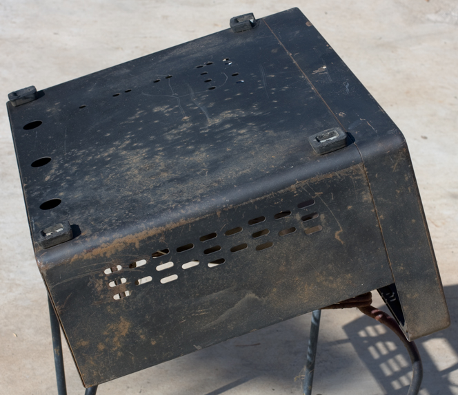
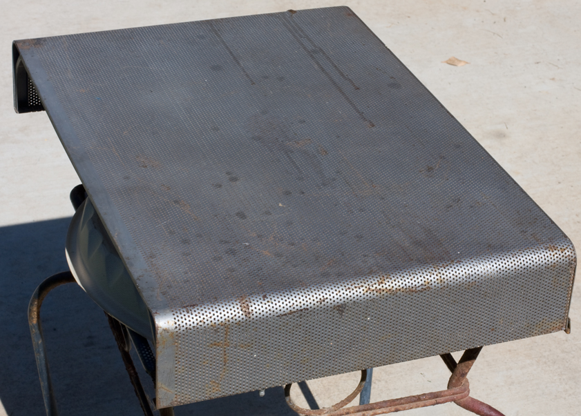
For the case bottom (left) I decided to start with flat black first and finish with Hammertone, as I wasn't sure how it would look with a lot of paint coats.
Feb 25 - Blood and Sweat
The case doesn't look too bad. Not as good as it should have if I'd worked harder on prep (I should have started with coarser steel wool and spent longer on the main body); but I can always do it again if it bothers me. Still it looks pretty good.
Putting it together was as dicey as I'd worried about. I figured I could try to slide it in horizontally and risk having something catch and gouge into the under-chassis where all the wiring is, or I could put it on its back and drop the chassis into the case downward, and hope I didn't pinch my fingertips off in the process. I ended up doing the latter, and came damn close. I didn't notice until I was running in the screws that there was blood on my screwdriver handle. But the cut I got is tiny; like oil, it only takes a little to make a big mess.
I bought some machine screws and washers, painted them black, and used them for the underside mountings. The flip-top went on with smaller machine screws, nuts and lock-washers unpainted. I didn't need to do it, but there are four places for screws and washers to bolt the front face into the cabinet. I'd opted for lock-washers but they're too small and look ridiculous (there's a huge ring where the old washer used to be), so I'm going to pick up some wide washers, paint them black, and use those for the front.
Fired it up and—it's a bit dicey. I was afraid that something might have jarred loose during the cabinet re-mounting, but now I think it's just the AVC and Limiter toggle switches being dirty, so I'll see if I can get them with contact cleaner without having to pull things apart again.
Still, when I could get it to work, it was doing well. FM broadcast, the usual assortment of evangelists, WWV on 5 and 10 MHz, a variety of foreign language stuff, and a few things in English. I think I got Radio Slovakia at 9.955. Also a fair number of SSB broadcasts that I can't demodulate. I'll have to see about getting an upverter for the SDR if I want to try sideband.
Final photo when I get the new washers and panel bolts in. In the meantime, this project is finished!
Feb 26 - More Documentation Now that I Don't Need It
The SX-42 "expanded" manual mentioned on Feb 19 arrived. It took awhile but it wasn't the seller—the USPS took its sweet time delivering it.
It's a loose-leaf, comb-bound print of the original operating instructions, and if that were all, it would be no big deal. It's a nice print but the free one on BAMA and elsewhere on the 'net are about as good. However, he's included the June 1947 Hallicrafters service bulletin 94X224 which I haven't seen. This guy did a nice job of scanning and trying to make a good print that you can actually read. It's not photographic quality, but it's good enough to do the alignment work. If you've seen the January 1949 service bulletin 94X317 (Run No.2) which is floating around the internet, you know that the scan is marginal and the part locations are illegible.
He also added the relevant pages from the Rider's Perpetual Troubleshooter (Volumes 18 and 19), which I hadn't seen, and he added Hallicrafters Service Hint #21.
Another really nice thing is the schematics. He's starts with a good, 11x17 print of Schematic 89D210K, which folds out. This is followed by Rider's copy from Volume 17 of the PTM, which is noteworthy because they print a copy of the RF section separately for each position of the band switch. I hadn't seen that one before, either. There are a number of Hallicrafters schematics floating around, but most of them are poor scans are don't bear close inspection. Even at 11x17, these are small but they're clear.
I thought it was a great $10 investment. If I'd known, I'd have bought it a year ago.
If you want one and the link I gave above has expired, try looking for seller Ziggy7.
March 1 - The Speaker
It's like it knew the radio was ready, so it made its way home. This is the first time I've seen one on the auction site I follow, so I figured it was providence.
This opens up a minor can of worms: last November 17th (and thereabouts), I was dithering over what to do about replacing the audio transformer and how to wire up the output terminals. Since I thought the chances of getting a high-Z speaker were nil, I ordered a transformer and wired the terminals for 4 and 8 ohms.
So it'll be interesting to see what happens when the "Announcer" (as Hallicrafters called it) arrives. If the speaker itself is bad, I can just replace it with a 4 or 8Ω unit and I'm good; it's also possible that a previous owner may have done it already. If it's the original 500Ω speaker, and if it's still good, I'll have to buy a transformer and add it in-between.
Either way, I'm hoping it'll arrive by next weekend.
March 6 - Together Again
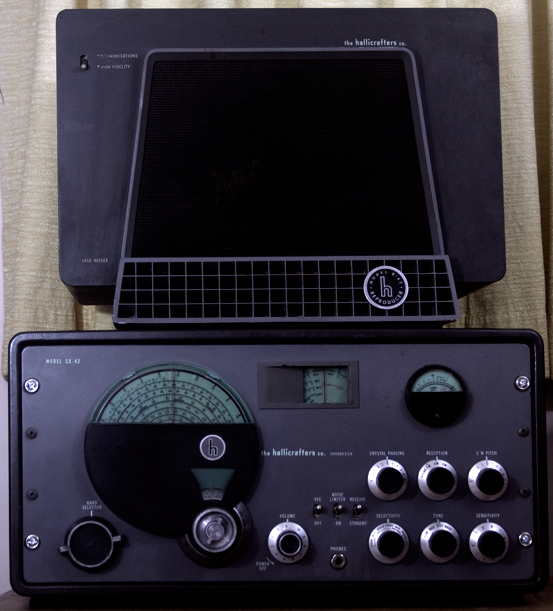 The speaker arrived today, so I wiped the top layer of grime off the cabinet with a rag and some Awesome. It did a so-so job on the cabinet but cleaned the Hallicrafters badge up nicely. Tomorrow I'll open it up and go over it in detail. I'll also photograph it. It has the original schematic label on the bottom; I've seen a few photos of this box on the 'net but never that. [I was wrong. BAMA has a fair-quality scan of it on their website, listed under R-42]. Someone may find it useful for restoration (if I don't accidentally destroy it first).
August 2021 - No audio
For quote some time I was having trouble with the audio. I'd turn it on and it would be dead. I'd switch between Send and Receive and after a couple of throws, audio would kick in. This got more difficult and finally ceased to work at all. I suspect the switch is bad. Due to the way the radio is made, the front panel is not the front of the chassis; most things stick through holes cut into the face plates but are mounted onto the chassis front (the headphone jack is the big exception here). If you want to remove a switch, you have to pull the chassis from the cabinet, then remove the front panel, and then you can access the switch. Oy vey.
The radio is currently on my bench as I try to disassemble it. It's been slow going as I have other projects going on, it's been difficult getting the knobs off (what a surprise), and it's the middle of summer and hot as hell, and I can hardly turn a screwdriver without breaking into a heavy sweat, and I don't like it.
Current status: no audio