
![]()
It's all been leading up to this. For me, 2013 is going to be the year of the Hallicrafters SX-42.
I hope.
 The Old Man found this at a swap meet; I don't remember when, but I'd say early 1990s. Paid around $40 for it, I believe.
This was before the Internet had anything other than scientific research info, computer info and pornography. We had to go to the central library downtown, look it up the SAMS index, and spent a chunk of change photocopying the Photofact package on those hateful just-good-enough library photocopy machines. Sent off somewhere for a bunch of orange drops to recap it.
And then—I don't know—it got set aside. It was moved to a far corner of the garage where it became home (probably not for the first time) to black widows and whatever else made the mistake of crawling in to get warm.
I've always wanted to get this machine running. It was in my head when I took the intro to electronics class. It's been in my head as I've read various books and practiced working on various radios. It was definitely in my head as we brought The National back to life. It was in my head as I studied for ham exams.
As I type this, I have no idea whether I'll be able to get it going again, or what it will need. I came across Phil Nelson's web page (Phil's Old Radios) devoted to his restoration of an SX-42. It's both inspiring and scary.
On a related note, I saw a movie called Love the Beast, by Eric Bana. It's about his love affair with an old car, the irrationality of loving a machine, and whether it's worth all the time, attention and frustration they demand. It's about cars, but you can extend it to other things as well. Some radios fit into that category.
Parts Sources and References
- AA1ZB.net: SX-42 restoration (includes modifications)
- BAMA (Boat Anchor Manual Archive): SX-42 manuals
- Mike Yancey: SX-42 refurb (link no longer works as of Aug 2021)
- Phil's Old Radios: SX-42 restoration
- Radio Boat Anchor Parts: parts for the SX-42
- Radio Museum: SX-42
- ShortwaveRadio.ch: SX-42
- W0YVA: SX-42 restoration (includes matching speaker)
- Ziggy7's Expanded manual for sale on eBay. Read my comments here.
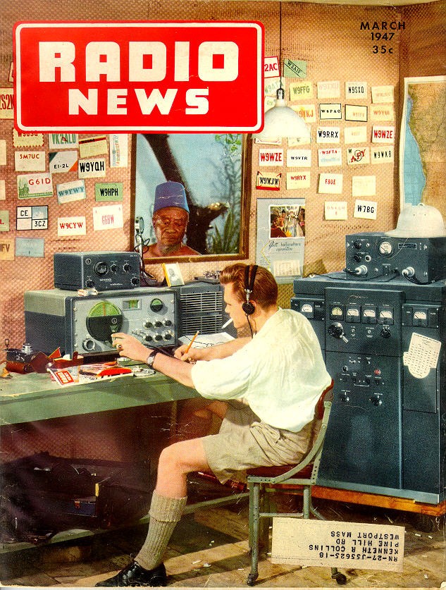
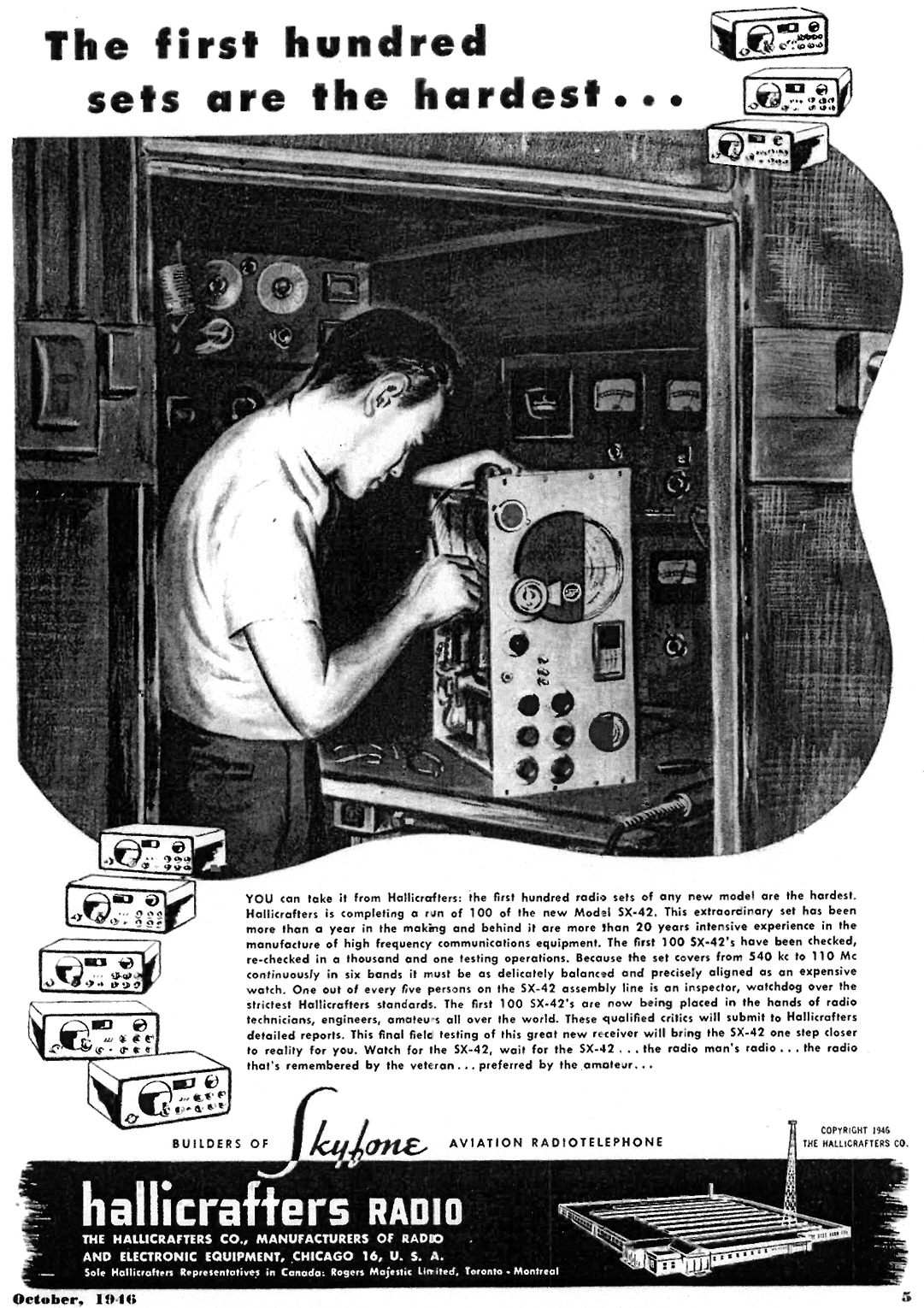
 A neat article written by Bill Halligan (that's why it's Halli-crafters) about the SX-42; from Radio News magazine, October 1946. Click on the PDF icon to read it.
Chassis Removal
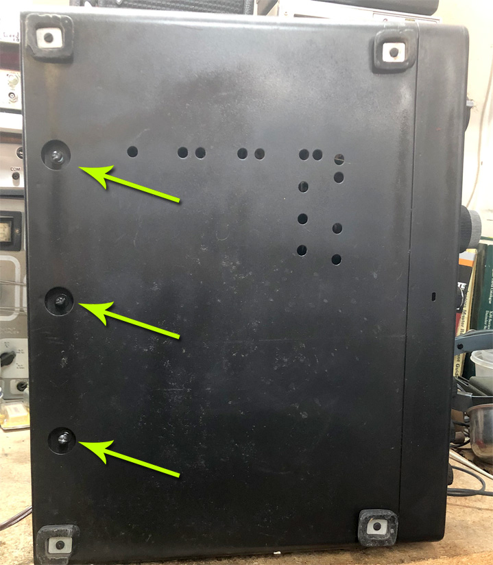
This is how to separate the chassis from the cabinet. First, set it on its side and remove the three screws underneath. Access holes are along the rear. (It's easier if you remove these three first, before removing the front.)
Now set it back on its feet and remove the four chrome screws on the front panel. The black screws can be left in place.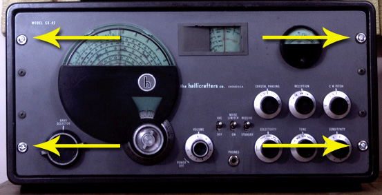
The chassis will now slide out the front of the cabinet.
Baseline
It's here—out of storage (a back corner of old man's garage) and now in a corner of my garage. This is what it looks like as of May 2013. The bad news is that it's filthy. The good news is that it's complete and there's no serious damage.
.jpg) |
|
.jpg) |
.jpg) |
Work on this is holding until I get some more done with the Airline battery radio, which is currently on the bench.
May 26, 2013 - Tube Checking
I'm stuck on the Wards, so I decided to decompress a little and checked the tubes. Replaced the one 6AG5 (back corner of the chassis) but everyone else checked out okay.
Tube Compliment
6AG5 (two) - RF amplifiers
7F8 - Converter
6SK7 - 1st IF
6SG7 - 2nd IF
6H6 - 2nd detector / Noise Limiter
7H7 (two) - FM Limiters
6H6 - FM discriminator
7A4 - BFO / S-meter amp
6SL7 - Audio inverter
6V6 (two) - push-pull audio out
5U4 - Rectifier
0D3/VR150 - voltage regulator
June 9, 2013 - Gojo
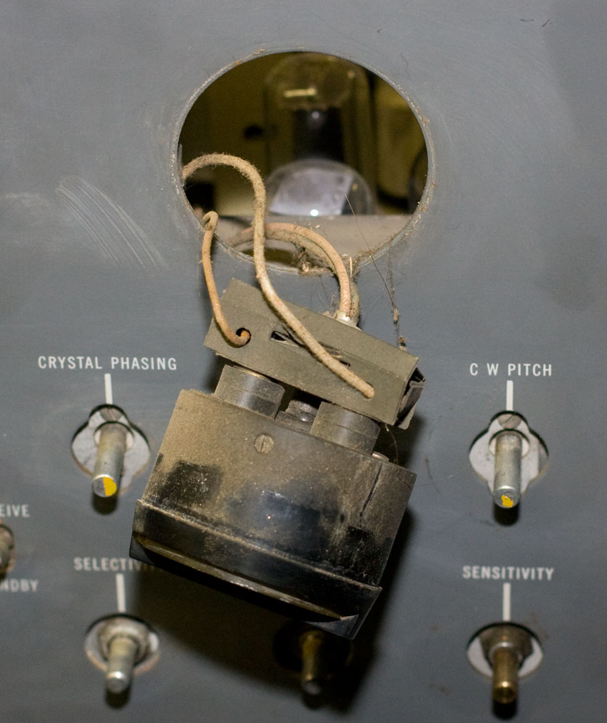
I'm only dabbing at this since I'm spending most of my time, energy and money fighting the Airline. I've been cleaning up the front with Gojo hand cleaner, and I'm getting good results. The Gojo is cleaning up the dirt and grime but not taking off the lettering. To really do it right, however, I'll have to take off the knobs. I made a (very) half-hearted stab at removing one but haven't found the right tool yet. I think it's a small allen wrech, but my garage is dark (and hot), the knobs are grimy and I haven't been able to get a good look in the holes to see. I'll have to roll it out into the sunlight sometime to get a good look.
July 21, 2013 - Knobs (Mostly) Off
.jpg) The photo here is for my own benefit and so that I don't repeat the mistake I made with the National; i.e. removing the knobs and then not being sure where each one goes. I'm not terribly worried—there are lots of photos of this thing on the internet. I was surprised to see how few really good photos there are of the National.
The photo here is for my own benefit and so that I don't repeat the mistake I made with the National; i.e. removing the knobs and then not being sure where each one goes. I'm not terribly worried—there are lots of photos of this thing on the internet. I was surprised to see how few really good photos there are of the National.
This one also shows the portion that I went over with Gojo and the portion that hasn't been cleaned.
Today I got most of the knobs off. As I type this the volume knob is still on, along with the switches and the tuner. There's a thing floating around the internet (though I got it from a radio club newsletter) that listed the effectiveness of various brands of penetrating oil. WD40 was ranked least effective (among those compared). Liquid Wrench and Kroil are better. But the best (by far) appears to be a 50/50 mix of acetone and automatic transmission fluid (ATF). Like many of these things on the internet, I suspect this is more wishful thinking than accurate, but what the hell. I mixed up some Dexron and acetone and made up a batch, drizled it into the screw holes, let it sit a little, and tried again.
 I don't know if the oil really mattered; I finally figured out the proper size jeweler's screwdriver to use, so I was able to get all the knobs off but one. So the volume knob is still there, and I'll try it again later. One of the problems is that the screwdriver is a bit too short and I can't get a good grip on the shaft to turn it, even with pliers. I'll either have to turn the chassis on its side, pull it forward so that it hangs over the edge of the cart (I like this idea least), or tilt it up and wedge something underneath. But it's about 500% humidity today and any time I do anything more strenuous than combing my hair, I start to sweat. So I'm going to let this bathe in oil a bit and I'll try again later this evening or tomorrow.
Almost forgot—the capacitors came. I went through the parts list and counted up what I thought were all the paper caps and ordered replacements. This time I went with axials instead of orange drops; they're more expensive but not too much (especially in the quantities I buy), but I think they'll look better when they're in. Orange drops are made PC boards and I never liked how they look on an open chassis.
Later note: regular knob set-screws use 1.5mm allen (hex) wrenches. Bandswitch and tuning knob set-screws use 5/64 allen wrenches (thank you, Phil).
October 28 - Next Time I'll Just Use a Hacksaw
.jpg) This has turned out to be like my National NC-173: one last knob that would not come off no matter what. I bought a left-handed drill bit to try and back out the set screw—no luck. Tried drilling it out with successively larger regular bits—no luck. Gave up to let The Old Man have a whack at it. He couldn't do it either. Finally got the thing pried off without marring the face or destroying the pot, but it was a close thing.
This has turned out to be like my National NC-173: one last knob that would not come off no matter what. I bought a left-handed drill bit to try and back out the set screw—no luck. Tried drilling it out with successively larger regular bits—no luck. Gave up to let The Old Man have a whack at it. He couldn't do it either. Finally got the thing pried off without marring the face or destroying the pot, but it was a close thing.
Now I have to figure out where we put the knob, because it's not in the box with the others.
November 2 - May 14, 1947
 Found the knob. It was in the box with the others, which is where it was supposed to be. That's why I couldn't find it. That and I can't count—or rather I was mismatching the shafts with the knobs. The band-switch knob goes on the shaft on the far left of the panel. Anyway, I have all the knobs (for the time being). I should put them in a safe-deposit box.
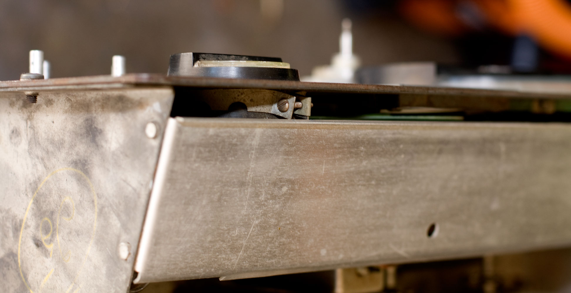
I figure the next step is to take the meter panels off. I decided to start with the easiest, which is the S-meter on the far right. That's held on by a cylinder clamp (for lack of the proper name for it). Took that off and I figured the black cover would slide off, but no — the whole meter comes out.
I tagged the two wires LEFT and RIGHT (from the POV of looking at the meter face) and removed the wires. They're covered by a nifty little paper box for who-knows-what-reason-why. Removed the lamp, and removed the meter. I think I can take the face off to clean it (I hope). Meantime I set it aside.
 Back to the front panel. I had thought I'd need to take the plastic facia plates off (the windows that protect the freq dials) but realized I probably didn't. So I took off the screws on the sides, the nut for the Phones jack, and then realized that the big tuning knob wasn't budging. It was held on with two set screws. NOoooo!
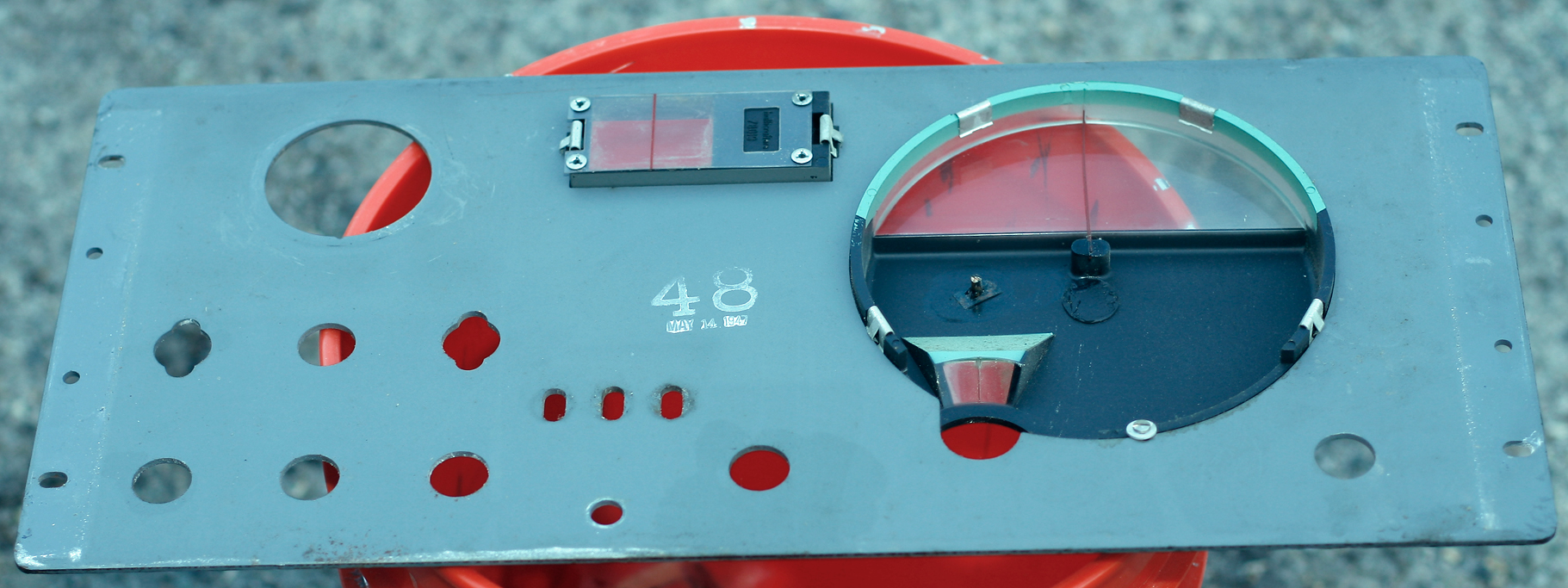
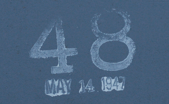 Happily, they loosened easily, and the front panel slid off nicely. I got to see the "birthday" stamp that I'd heard other owners talk about. Mine's May 14, 1947, which makes it 66 years old. Write your own joke.
So here's what the chassis looks like now. The freq dials look good!
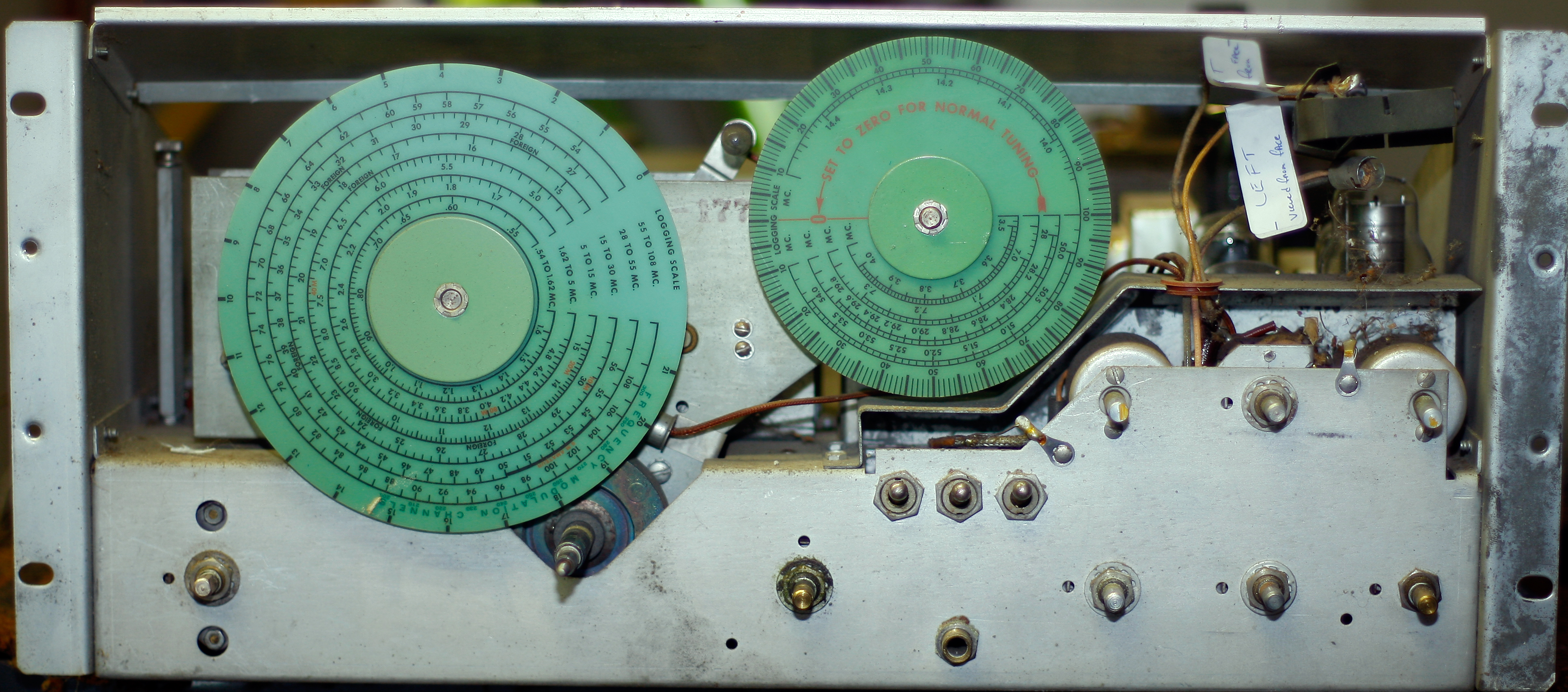
The next step, I believe, will be going over the electrical.
November 16 - Too Many Wires
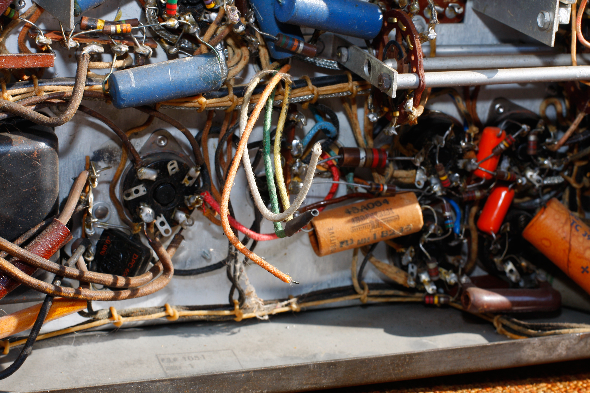 So the first thing I noticed, and it's so obvious that even I saw it right off, is that there are several disconnected wires. Initially, I thought they'd simply broken off somewhere and it wouldn't be a tremendous deal to find out where they go. But no...
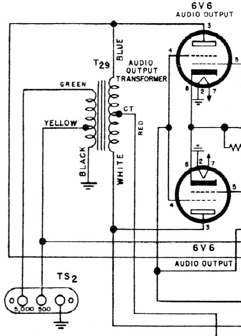
Long story short: they're from the audio transformer. There are two holes in the chassis. Wires from the primary side feed through one hole, and wires from the secondary feed through the other. Now the problem begins to come into focus: this isn't the original audio transformer. I can see where the primary wires have been patched in. I can see where at least two wires from the secondary have been connected. Unfortunately, I still have four more wires that are not.
 And there's a sticker on the transformer that has tells voltages on each wire color, and it's The Old Man's handwriting. Of course this was done 20 years ago so neither of us is going to remember any of it.
So what to do with the extra wires? Two are taped together, my guess is he figured they weren't going to be used. But the other two go where? The schematic makes it pretty plain, but the colors on my wires don't correspond.
This receiver doesn't have an internal speaker; it only has speaker output terminals. There are three: one is common (ground) and gets used regardless. The other depends on which speaker impedance you have: 500Ω or 5000Ω. The original Halli speaker is 500Ω, but I don't have one.
Anyway, back to tracing. Since the speaker posts are on the rear of the chassis and the audio output is in the middle, they run wires from the posts along the chassis wall and bring them up to a set of tie-points near the transformer. Common is ground, so that's no problem. I then identified where the 500 and 5000 post tie points were.
The 500Ω tie point had a wire hooked up that appeared to go into the transformer. The 5000Ω point had a wire that went off to the switch, which on the schematic was supposed to go to the 500Ω post, so something's backward. Meanwhile the 5000Ω tie isn't connected to the transformer. Okay; maybe we figured we'd hook the transformer to the 500Ω lead, forget the 5000Ω post, to hell with the switch (which is the tone control, and I have no idea what that's supposed to accomplish). Okay, fine. Except for one thing: the 500Ω and Common posts are shorted.
Where are they shorted? I dunno. There's nothing obvious that could see. So is it an internal short in the transformer, or is something else wired funny? What are these wires supposed to be anyway? A google search on the part number for this transformer turns up nothing. Likely it came from The Old Man's junk box anyway.
It's giving me a migrane. I figured I'll yank it, get a transformer I know, and wire it in "properly." I thought I'd just get another Halli audio transformer but so far, no such luck finding one.
And there's still the problem of the speaker. What I'm going to have to do anyway (and if I read it correctly, what Hallicrafters did) is take a modern 4 to 8Ω speaker and hang another matching transformer on it. So I began thinking that rather than have two transformers (one in the receiver and another in the speaker cabinet) I may as well just go from ~6000Ω to 4Ω directly and be done with it. One of the Hammonds (I think it's a 125D using their secondary lugs 1 and 4) would do it. I would just have to make a note that the output impediance at the speaker post was 4Ω instead of 500 and 5000Ω. $40 from Mouser.
I can use the National's speaker which is 4Ω. Yes, it's putting a Chrysler muffler on a Buick exhaust. If I could add some Hammarlund and Collins stuff I'd make a real Frankenradio out of it. I like giving the purists heartburn.
November 17 - Do This With the Garage Door Open
This morning I woke up and the first thing I thought was, it's one side of a transformer, you idiot; it's a coil—of course it's a short. DUH.
 This is discouraging. At best I can say it's book learning vs. application. I know this but I can't seem to apply it when I see it.
So that means, in theory anyway, that the transformer is hooked up, extra wires be-damned. So try it? Sure, why not. Opened up the garage door in case there was smoke, and hopefully one of the neighbors might see me if I'm electrocuted. Plugged it in via the Variac, stuck a knob on the On/Off Volume switch, plugged in the Halli (I'll have to replace the cord, it's disintegrating) and fired it off.
No sparks, no snaps, no smoke.
The dial lamps lit. I'm missing one (they're #44) but the others, to my amazement, glowed. I stuck a 47 in temporarily until I can get replacements. This is modern life: I can get a box of 10 for $4.50 but I'll have to pay another $5 for shipping. Or I can get two for $3 from Radio shack.
Slowly ran up the Variac until I got full power. All the tubes appear to be lit. Even the 5U4, whose filament I can't see, was warm. So I've got power and nothing's frying. That's good.
Sound? Once again, amnesia sets in and I use lead clips to hook a loose 8Ω to the 500Ω output. Nothing. Tried hooking up the meter to see if I could get read any voltage across it and got nothing useful.
Okay, what about the headphone jack? I've got a set of High-Z headphones somewhere...........
Don't know what I did with them. They're around here somewhere.
Finally decided, as a last step before I confer with The Old Man, to take the temperature of the two 6V6 output tubes. SAMS says pin 3 should be 280 and Pin 4 should 250, and I got 270 and 250, on each. So they're healthy, at least.
So there we are, until I figure something else out.
November 23 - There's a Reason It's Called an S-Meter
The Old Man concurred, so I went ahead an ordered a Hammond 125D transformer and a handful of #44 bulbs from Mouser. Since it would take awhile to get them, I thought I would try to keep momentum going with something else. So I put on a new AC cord since the old one was disintegrating (I'd had to tape the plug itself together just to plug it in). I used a clock oiler to lube as many bearings and friction points as I could find. Spritzed contact cleaner on the wafer switches.
Also replaced a 100μF electrolytic that was a dead short (C127, if you're keeping score on your Hallicrafters schematic; Item 17 on the Photofact), and since it was right next to it, I replaced the old 0.25μF paper cap that may or may not have been bad, but it's a paper cap so what the hell.
Then I decided that what I really ought to be doing is cleaning the plastic so I can put the face back on, then I can put the knobs on, and it'll be easier to know what I'm doing later on with the electrical restoration.
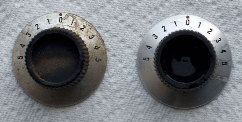
The plastic polish I have is detailer, just glorified water, and it was too late to go out and buy proper cleaner, so I decided to try toothpaste instead. That's a classic plastic polish. It worked so-so. I'll end up getting proper polish later.
I also came across the Service Bulletin, skimmed it and noticed there was a section about dial lamps. And there's an interesting piece here that I'm very glad I read:
Replacing Lamps:
There are three dial lamps and one meter lamp. To replace the lamps, it is necessary to remove the reciver chassis from the cabinet and remove the light shield across the top of the dial drive mechanism. . . . Replace the dial lamps with 6-8V. 250 mA GE #44 (Blue bead) lamps or equivalent. The meter lamp is removed by pulling the socket straight out of the grommet. Replace this lamp with 6-8V 150 mA GE #47 (Brown bead) or equivalent. Do not use a 250 mA lamp in the meter housing as the excessive heat will discolor the meter scale. Refer to the Service Parts List for recommended lamps with a green tint.
I'm not even going to try for the green tint. What I took away from this was, it needs a #47 bulb—I've got #47 bulbs. I can do this now.
I know this in hindsight now: the bulb is held in by what was probably a rubber grommet that was, 66-½ years ago, pliable, but now has the qualities of week-old french bread. The outer half broke when I pulled the old bulb out. The inner half broke when I tried to push new bulb in.
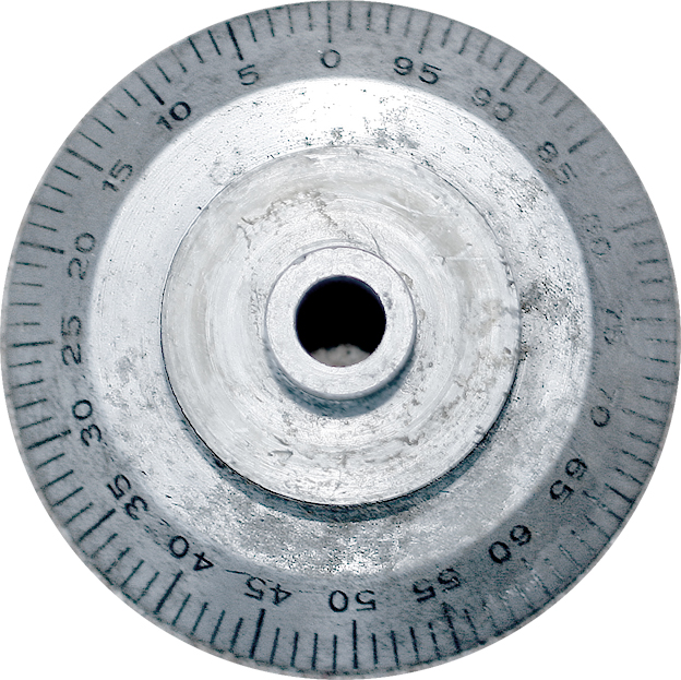
Lovely. I hadn't planned on it, but since I now had debris in it, I might as well take the meter apart. I didn't know this at the time so I'll mention it here. To take the case off, remove the three screws on the side of the case (at 12, 4 and 8 o'clock positions). The two screws on the rear panel hold the movement to the back panel, and should be left there until you have the case off. That'll help protect the needle and the watch-like movement from damage. The screw on the front panel (at the 6 o'clock position) is for zeroing the needle. Leave that one alone.
I blew the debris out with a hand-squeeze blower bulb that I use for cleaning digital camera sensors. 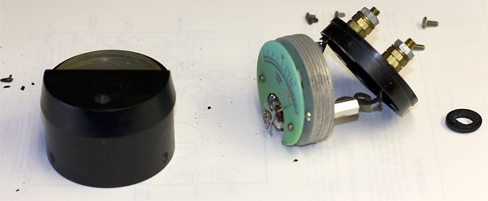
On the left is the case. The middle-right is the meter movement and the back panel. The black spots are debris. The ring on the far right is a half-collar that I'd super-glued together just to see if I could even think about pushing a lamp throught it—no way. A #44 wouldn't fit either (by this time my package had arrived).
It appears that this is the grommet that will fit: Keystone Electronics #745. 3/8" i.d., 1/2" o.d. But I ended up getting it from Radio Shack, which surprised me by having them (as part of an assortment).
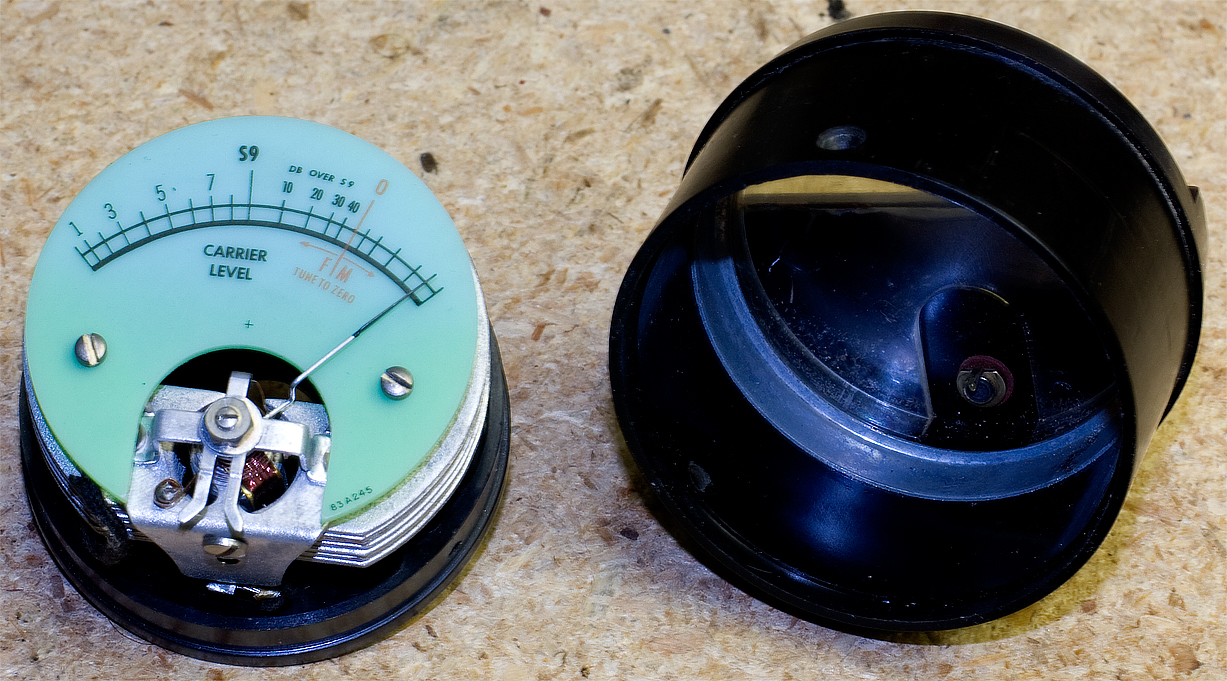
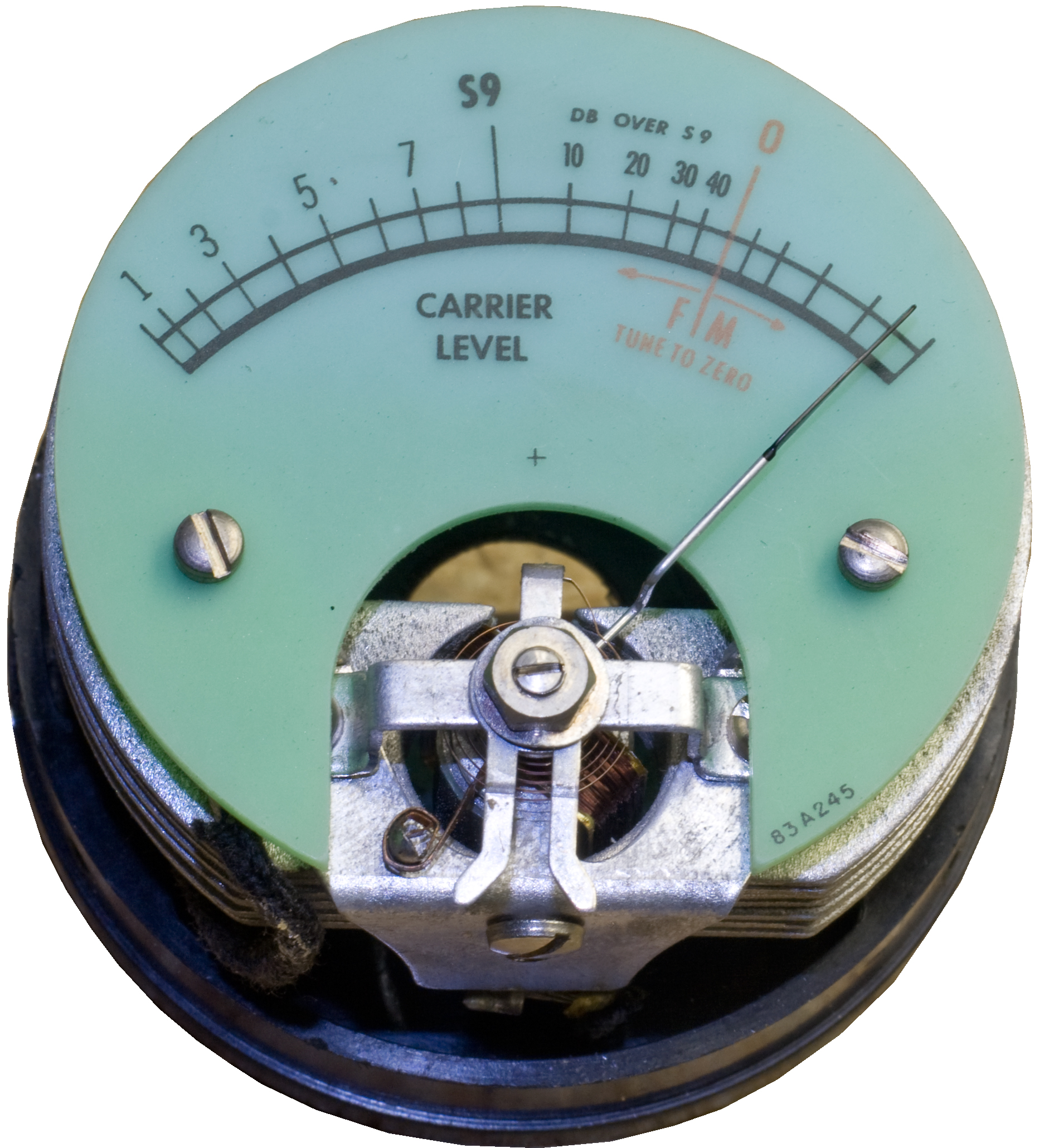
Here it is again. Click on the images for larger versions. The left is the meter movement with the outer case next to it. The right is just the meter movement with better detail. See the forks on the movement? They're pointing downward like walrus tusks: this mates up with the screw bracket in the front of the case; when you turn the screw it pushes the forks a little bit either left or right, and that's how you zero the needle when it's at rest.
Picked up some Meguiar's PlastX clear plastic cleaner and polish. Not a miracle worker but it cleaned up the dial glass nicely. I'll also do the same for the other plastic windows.
Nov 24 - The New Audio Transformer Goes In
The new transformer went in surprisingly easy (knock wood). Helps to know which lead does what. That done, I put some knobs on and got it ready to fire up. Somewhere, as I muscled this thing around (it would be nice if I had lazy susan on the workbench), I leaned on the 5U4 and thought I heard a tiny crack. Pulled it out and saw that the plastic center pin had broken off, revealing the bulb stem. I put it on the Hickok and it tested fine, and put it back in. That takes some effort since the locator pin was gone, and as I type this I think I got it wrong.
Fired it up and nada. Nothing. Suspicious of the 5U4. For once, I happened to have some in stock so I swapped it out. This one I could see was lighting (the other one is silvered over on top so you can't see the filament glow).
Nothing . . . until I tapped the volume control. Noise! The audio out definitely works. Tried different bands and different settings but nothing, not even white noise. I began to crank the tuner and a loud hum, like AC hum, kicked in. Turned it off, then back on again. No hum. Turn turn HUM.
At any rate, it's alive. There are problems upstream but at least the audio out works. I can start back-tracing. But it's alive.
Next up: put the face back on, with knobs and the S-meter and the whole she-bang. That will protect the plastic dials, which are dangerously exposed, and make it easier for me to set switches during troubleshooting. In the meantime, this is a good stopping point.