
![]()
Note: this radio is no longer in my collection. This page will be removed in late 2024.
I remember once asking The Old Man, who was an electronics tech who repaired this stuff, which the best brands were. It's a tough call, but he eventually said Admiral. (The other half of this was a comment that he thought Zenith had the best quality control. If you took a roomful of televisions from various manufacturers and adjusted them all, most of them wouldn't match, but the Zeniths would all look the same. They might not have had the absolute best picture, but they were consistantly good.)
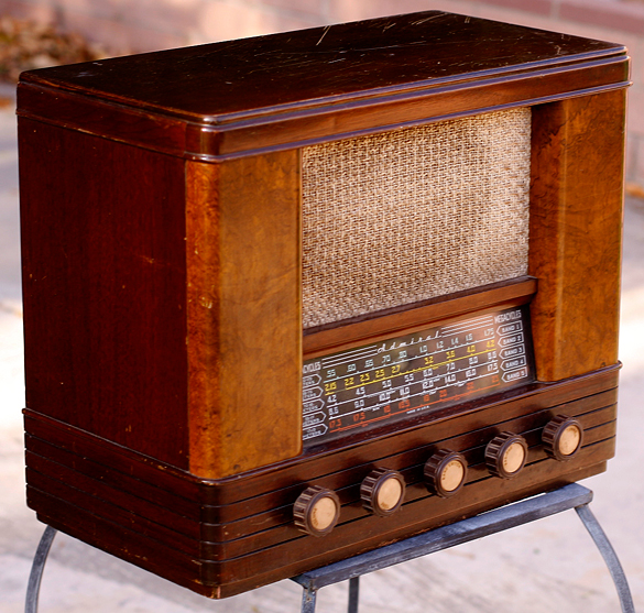
 I've had an eye out for an Admiral of some sort, and this caught my eye. Truly, I would have bought it no matter what brand it was because the cabinet is beautiful; the fact that it was an Admiral was gravy.
This showed up on an online auction site; I threw in a bid, figuring I'd be outbid but at least I'd had my hand in, and was shocked to find that I'd won. Afterward I figured I was probably really bidding on an empty cabinet, or that there was some other gross defect that I didnt know about, but it arrived complete, intact, and in damn good condition all things considering. It even had all the knobs!
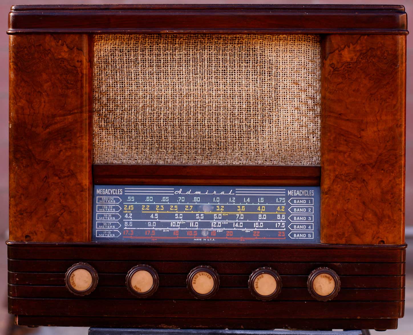
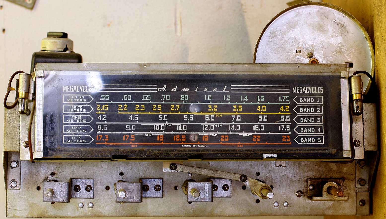
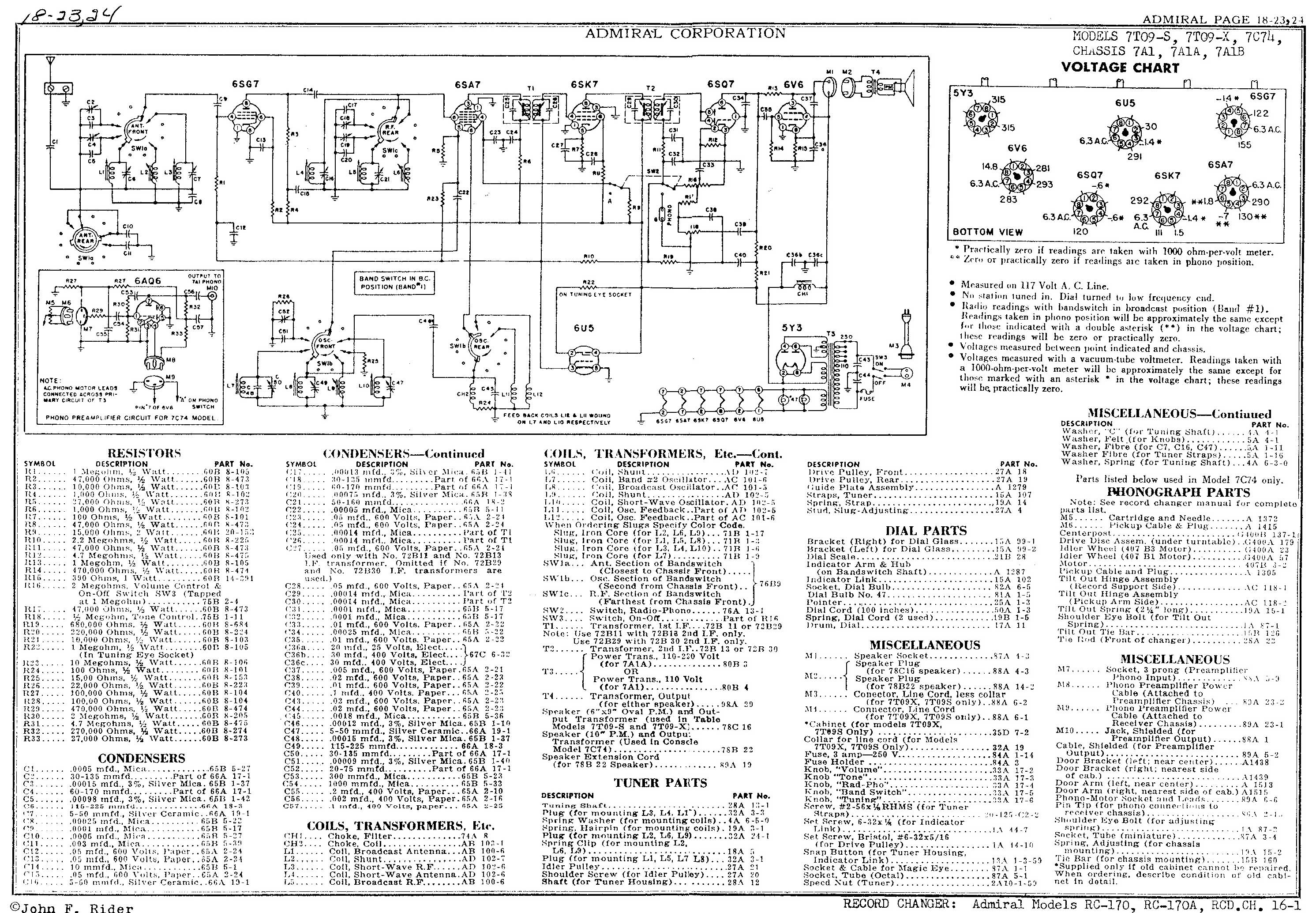
 Almost everything I know about this comes from the Radiophile website. They describe it as an "odd hybrid" of consumer radio and communication rig, and I agree. It's big (19x15x9), it's got the two-tone wooden cabinet with what I believe is burl-walnut on the sides, five bands on a slide-rule dial, so it turns from 540kHz continuously (except for a small gap around 2MHz) up to 23MHz. Yet it's not a real communications radio: there's no bandspread or way to handle code; more importantly, inside it's an All-American six with a transformer (whereas most communications rigs have a lot more tubes). A look at the schematic on Nostalgair shows that it's surprisingly uncomplicated.
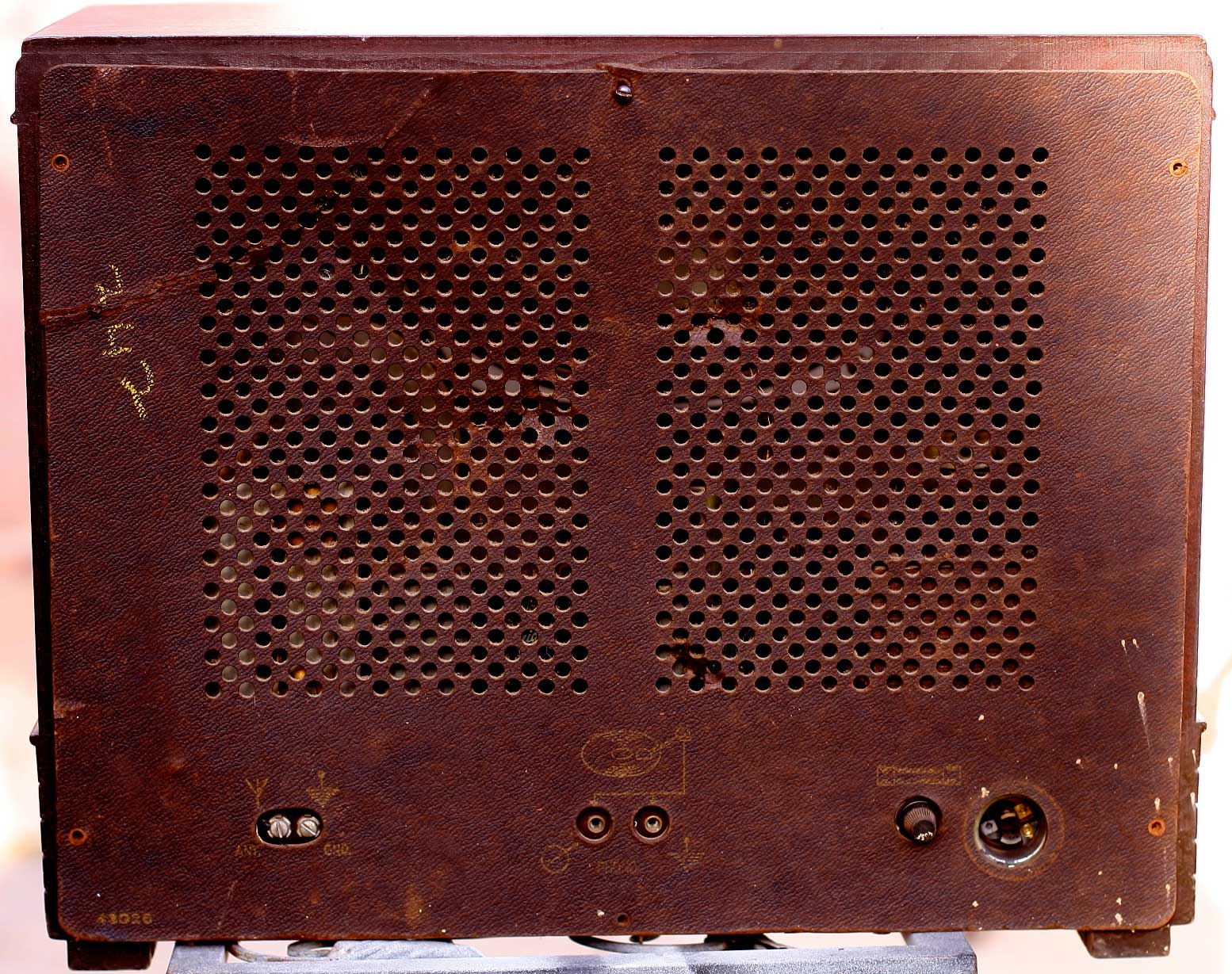


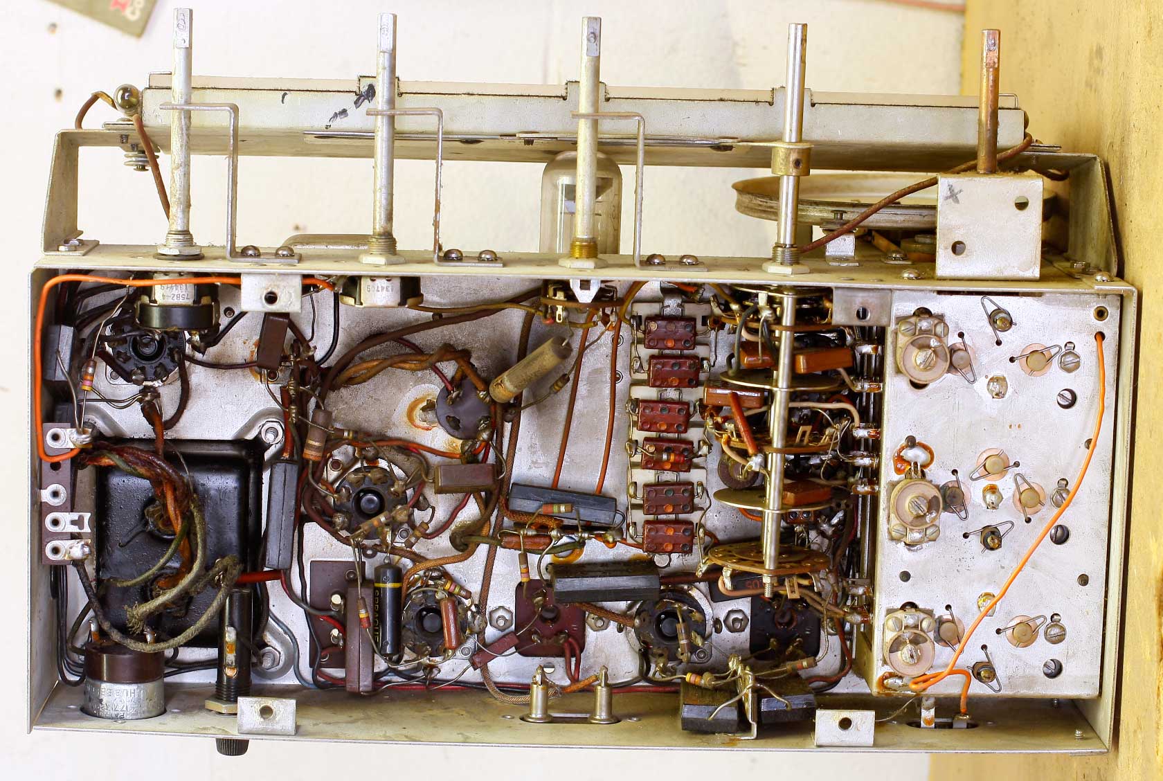
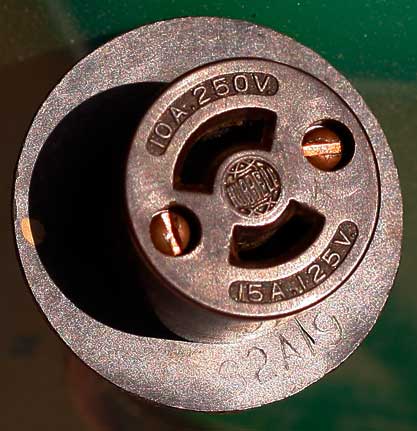
So far (and that's bad) the radio's been a dream. The knobs are plastic and all held by set screws so they pulled off cleanly and easily. Removed four screws on the bottom and the chassis slid out. A first for me: the speaker leads plug into the chassis so I didn't have to unsolder anything. The only real problem was the AC wire whose rubber insulation was disintegrating. The special plug on the end unscrewed nicely and stayed in once piece, so I was able to swap out a brown lamp cord and it looks fine.
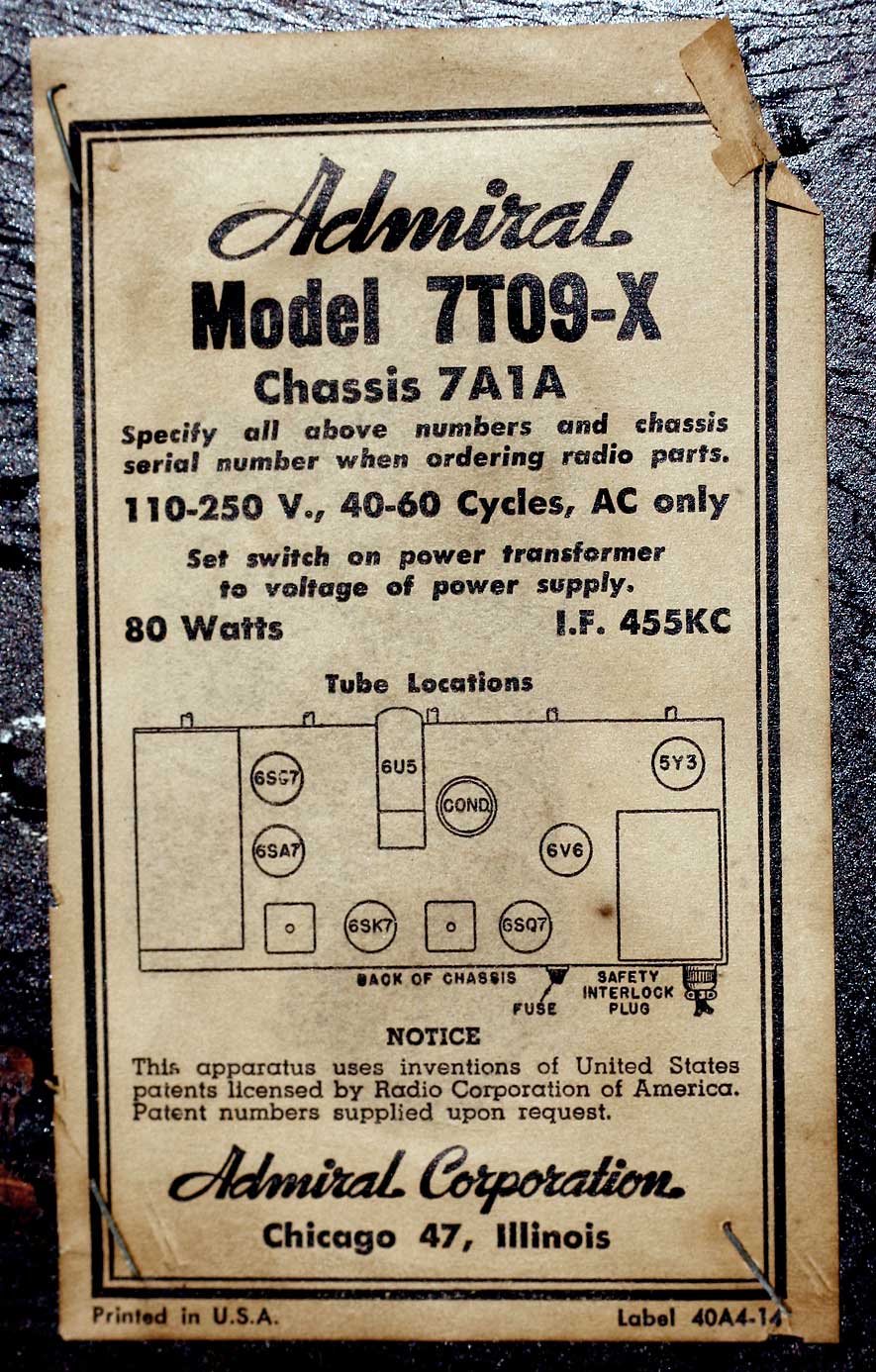
Tube Compliment
6SG7 - RF amp
6SA7 - Converter
6SK7 - IF
6SQ7 - 2nd Detector
6V6 - Audio out
5Y3 - Rectifier
6U5 - magic eye
So Does It Work? Of Course Not
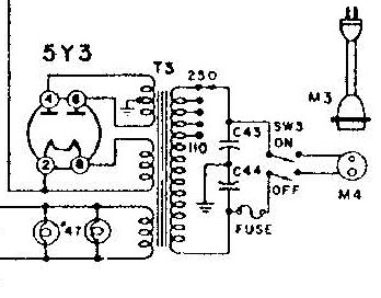 The Old Man had suggested that I preemptively replace the two AC bypass capacitors (C43 and C44 on the diagram here) because if and when the failed, it would create a shock hazard. I have finally built up my parts box to the point where I can find parts I need without having to mail order every single thing. There are three paper 0.02 μF in the same area so I replaced them all.
I didn't want to re-cap the whole thing up-front just in case I introduced more problems, so I decided to try and do things in increments, so I wanted to see if it ran. As this is a transformer supplied radio (as opposed to a transformerless rig where the tube heaters are wired in series), I pulled the 5Y3 rectifier and turned it on to see if the radio would light. Removing the 5Y3 allows power to go to the tube heaters but removes the rectified high-voltage supply to the rest of the system. I looked and listened for shorts, smoke, pops and any other nasty surprises but didn't find anything. Except that both dial lamps were burned out.
 With the 5Y3 back in I turned it back on and again, no smoke, no pops, no arcs or other nastiness. There's a little AC hum but not near what I expected, so I can put off restuffing the filters until later. The 6V6 is the audio final out on this system, and it lit (it's glass. The rest of the tubes were metal-envelope so I couldn't see the filaments), and I had noise when I touched the wiper on the volume control. The audio stage seems okay, must be RF. Even the random-wire antenna I was using (literally a wire running the length of the garage) should have given me something.
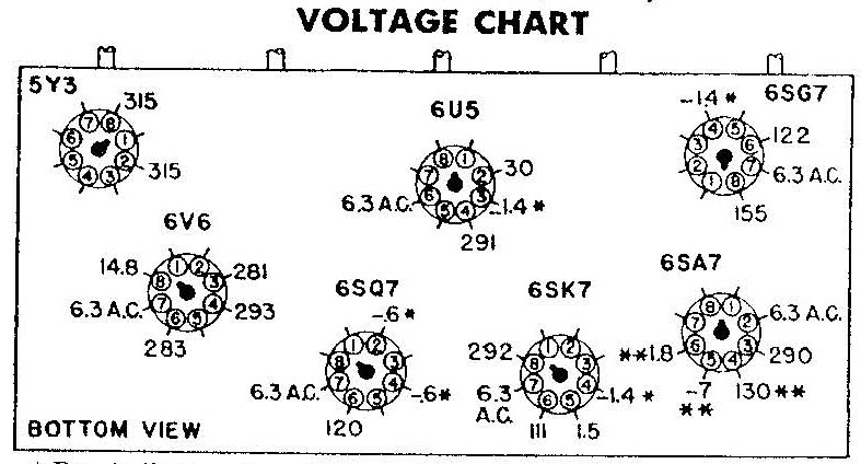
 So I began checking voltages, and immediately found that the plates on the 5Y3 were about 140V, where I was expecting 315V (see the chart above). Now what? I checked everything over—the caps I'd replaced were where they should have been; my soldering is getting better so nothing popped apart; no broken wires, no obvious shorts. Voltage readings elsewhere were also about half what the chart was calling for. The problem must be around the power supply.
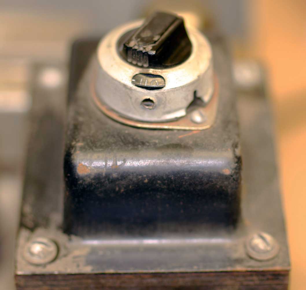
Finally a call to The Old Man, who directed me to the schematic of the transformer. There are numerous taps off the primary; maybe a previous owner had the radio set up for a different line voltage. That's what it turned out to be. I hadn't noticed it before, if on the top of the transformer there's a rotary switch and a little indicator with various voltages. Previous Owner had it set to 150. I rotated it back down to 110 and read voltages. Now I was back to acceptable (albiet a little hot) voltages.
About the same time I put the knobs back on so I could easily adjust the controls, and realized that I had the source selected to PHONO. Funny how not having the RF stage connected to the audio will keep you from getting radio signals.
I borrowed my friend's ancient Sylvania tube tester and ran the tubes. The 6SG7 RF pre-amp was weak and the 6SA7 mixer was dead. Here I was extremely lucky; the same friend with the tube tester had bought a box of tubes at a yard sale for me, and among them I harvested a batch of useful radio tubes, including both the SG7 and the SA7. They're cheap enough from Tube Depot, but at least I wouldn't have to order and wait a week for them to arrive. It's so nice to have inventory!
So with the power supply corrected, a set of working tubes, and the source set back to RADIO, I was able to pick up white noise and a couple of stronger stations. So I'm back in business again. What next? The hum is still at an acceptable level. How about the eye tube? That's dead.
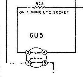
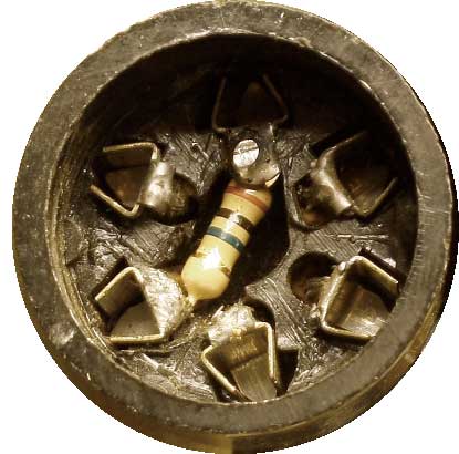 The Old Man had directed my attention to the 6U5 "magic eye" portion of the schematic to the resistor (R22 on the diagram to the left), which he says is notorious for failing. It's a 1MΩ ½ watt resistor that's located within the eye-tube socket itself. If you look inside the socket, there's a flat facia plate that covers the pin sockets; there's a key and a notch so it only goes one way, which is necessary because two of the pins are physically larger (the heaters), and it provides protection so you don't inadvertantly plug the tube in incorrectly. Anyway if you lift this plate out (mouse over the image to the right), it exposes that little 1M resistor which is soldered between Pins 2 and 4. Happily, 1MΩ ½ watt resistors are cheap and easy to find, unlike the 6U5 itself (Tube Depot wants around $60 for it; Tube World has some for $45).
So I swapped out the old resistor (it was open), verified that the new one worked, plugged everything back in and fired up. The magic eye works! That was a relief.
Alignment and First Restringing
Recapping looked daunting as a few of the caps looked buried, so I thought I'd do a preliminary alignment and restring the dial cord. Aligning the IF went easy, but quickly I got stuck when the alignment instructions required me to tune until the pointer was at 1300 kHz, and I had no pointer because I hadn't strung it.
The last restringing (the Airline 84WG) went easy so I was confident, and things were fine until the cord slipped on the tuning axle and I couldn't find my bottle of rosin. I've recently moved, and I have no idea where it is. It may still be at The Old Man's house, or it may be here somewhere. I've turned the place upside down looking for it but it's still (as I write this) AWOL.
Antique Radio's Forum had some interesting threads on alternatives to rosin, one being spray contact cement. I happened to have some, so I sprayed some into an old spice-bottle cap and applied it to the cord. Worked like a charm.
Until it walked off one of the pullies. Again and again and again and again. No matter what I did, it kept walking off the pully. Adding tension, reducing tension, adding turns on the axle, reducing turns, nothing worked. Ultimately I decided it was too gummy, because like hair gel, cologne and shoe-polish, if a little is good then a lot is far better, and I'd been pretty liberal with the stuff. So I cleaned the metal parts with Goo Gone, the brain-meltingest stuff I've ever smelled (including formaldehyde), and restarted with clean cord.
No good. Still won't work. The way I see it, the problem is that the plane of the pully (the problem child) is at maybe a 15 degree angle to the plane of the tuning axle and the big pully that's connected to the tuning cap; so the thread walks around as it turns and wants to go off the pully. This would be no problem if there were a bend in the shaft the pully rides on so it were in the same plane, but no.
I'm got two different sized dial cord threads and I used the thicker one, which I thought was a closer match to the original thread; but next time I'll try the thinner one.
Recapping
The radio is working but I'm not happy with it; I thought reception was weak on commercial AM where I figured it would be easiest to pick up broadcasts. Some of this may be my new location, which as usual is in an area where AM and my favorite FM stations are spotty. In lieu of putting up a proper antenna (it's on my list of things to do, but some other things have to happen first), I thought I'd replace a couple of the easy-to-get-to paper caps, figuring that it may help here and there. By doing one or two at a time, I managed to get through them without too much trouble; even the one that was truly buried wasn't too difficult, and I think the radio sounds better as a result.
One of the nice things about it, and I'm not entirely sure where it occurred, is that it picks up SW fairly well. Even during the day I was able to pick up a couple items on Band 5 (17 to 23 MHz), and in the evening I picked up something on all the bands. Commercial AM is still weak to my ears, but we'll see. If I can get it restrung and do the full alignment, that may help.
Second Restringing
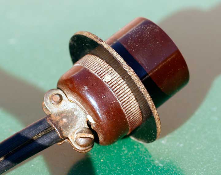
I used the thinner dial cord and tried again, and this time it seemed to track properly without coming off the little pully. Now the problem was the lack of stickiness, as the tuning axle shaft spun under the cord winding. This time I went to a local music shop and bought a small block of resin. Bill Turner, in a thread on AntiqueRadios suggested mixing rosin with denatured alcohol. As Bill Turner is the guy I originally bought the rosin mix from, I figured he knew something. But I didn't have denatured alcohol, didn't want to buy a jug just for this project so I tried the isopropyl alcohol I keep in the medicine cabinet. Initially I put in a small amount of resin (a "pea sized" chunk plus debris, since the rosin is very hard, brittle and shatters when you cut it) in probably 4 fluid ounces of alcohol; I used the only empty glass jar I had, which was an old cumin spice bottle.
Initially it didn't look like it was going to desolve, but after a few hours it did. It was way too weak. Ultimately I ended up putting about half the rosin block in, and that gave me a nicely amber-colored mix of sticky rosin. I painted the cord and the shaft (which I also scored a little with a pocket knife), and that did the trick.
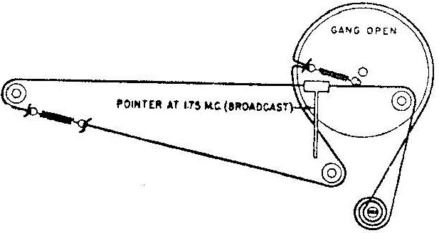 Another problem has arisen which I haven't fixed yet. The way the dial is strung is that there are two springs, one on the big pully attached to the tuner, and another one between two small pullies behind the glass dial. I'm not sure why, but the cord turns nicely when I go down the dial (right to left, or in descending frequency), but when I go the other way, only one side of the thread pulls, that little spring between the two pullies expands, and cord doesn't move for maybe half a turn, then finally things start moving. The result is if you're tuning up-dial, when you stop the knob springs back, counter-clockwise, and the needle and the air cap all settle back. That makes tuning a pain. Until it finally stops turning (and slides) along the axle, or walks off one of the pullies.
I'm not sure what to do about it. Maybe a stiffer spring. Honestly I'm not sure what that spring is supposed to do anyway.
Regardless, that was good enough to get going. I painted the pointer with nail polish. I'd just guessed when I was at the store looking at polish colors, but it turns out to be pretty damned close, at least in the mediocre lighting of the garage. When it's in place behind the dial I don't think anyone would ever know the difference.
Third Restringing
I was due to visit the folks so I took the Admiral chassis along. That was an eye-opener. First off, we tackled the string. I really thought that the problem was that the tuning section (i.e. the big wheel) was too stiff and required too much torque. Didn't really help. What did the trick was actually two things.
The first was that he didn't like the two-spring setup (see the diagram) and he didn't like how both ends of the string tied to the same point (on the string on the big wheel). He liked it better when one end tied to the string and the other to a point elsewhere on the wheel and that helped.
The other part turned out to be a problem with the tuning coils...
Tuning Coil Repair
 I thought this had a tuning capacitor with two sets of plates, the only difference being that the plates moved vertically instead of rotating. Nope—I had coils, six of them that are permeability tuned. The core is attached to the top, which moves up and down as the dial is tuned; the coils are attached to the bottom and stay in place.
I had two coils that had come off their mounts; one was just floating and easily replaced; the other had broken off where the two tiny wires attached. Once that was resoldered back and the coils in place, the tuner worked fine. Now for an alignment.
Second Aligment
That took care of my complaint that the set was weak. Amazing what happens when the tuning coils are set up properly. I'd hoped the dimness of the magic eye would also be cured, but no such luck; we swapped it out with a better one that the old man had in stock. I kept the old eye as a backup (they're expensive).
We tried aligning it again but with only middling success; we seemed to be chasing birdies. This is one of the very few (only?) times I've had better luck at home. I ended up doing it again at home, this time with the benefit of setting the signal generator with a frequency counter (The Old Man doesn't have a freak counter, so we're not completely sure how far off, if any, his signal generator is). I still can't get the thing to track as closely as I'd like, but it's good enough. I keep telling myself that this is a good project to revisit later if/when my skills improve.
That leaves —
Cabinet Refinishing
I don't know much about wood. I took one semester of wood shop in school. I can saw and drill and do basic stuff, but that's about it. I've been reading up on refinishing cabinets (there are two interesting articles here) but decided this wasn't the cabinet I wanted to learn on--it's really not in bad shape. I ended up buying Howard's Restor-a-Finish and Feed-n-Wax, and the cabinet came out nice; certainly nice enough for my purposes. Some time I'll find a radio with a terrible cabinet for a reasonable price and I'll try out the refinishing techniques.
So this morning I put the chassis back in the cabinet, put the knobs on, screwed the cardboard back in place, and done. I haven't bothered to photograph it since it looks pretty much like the original photo. Most of the effort went inside where you can't see it.
Now all I have to do is figure out where to put it.