
![]()
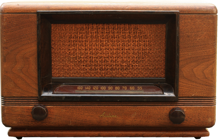
I worked for Montgomery Ward for awhile. Even though the company was senior-managed into bankruptcy by monkeys (hence its nickname), I always thought Wards had the charm of a 3-legged dog. Airline was Ward's house-brand, so I snagged this for a good price—about $10 plus shipping. It's got a solid wood cabinet, not faux-woodgrain plastic, and while it's not the most stylish thing they ever sold, it seems very Airline-ish to me.
Fall 2011: arrived complete but with a broken knob (replaced with something close enough. This will never be a museum piece). The tubes appear to be original and the serial numbers are 1951, so I believe the radio is probably from around that year. Played decently but with some hum, so we added another filter capacitor in parallel to the dying stage, and that cleaned it up. The other main problem is the broken dial cord, which I replaced. The cabinet is also a little rough and the slide-rule dial is grimy, but I think some cleaner/polish will bring it back to life.
January 2012: it developed more hum. One of the 50µ filter caps is going, so I'm going to try my hand at redoing the can. It's a three-stage filter, two 50s at 150V and one 20µ at 25V. If it still plays after I've done that, I'm going to go ahead and recap it. I bought these things to practice these skills: it's time to start doing it. Plus I'm between projects at the moment, so it'll hopefully keep me from buying another project radio.
Capacitor Restuffing
I came across an bad filter cap that I'd pulled out of another radio and decided to use it as a cadaver. I sliced it lengthwise down the back (180deg away from the writing) and found it realitively easy to peal open and remove the guts. So I decided to try it again on the Wards cap.
As always, click on an image to see it larger.
Removal and Disembowlment
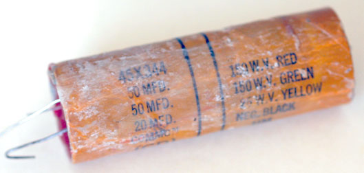
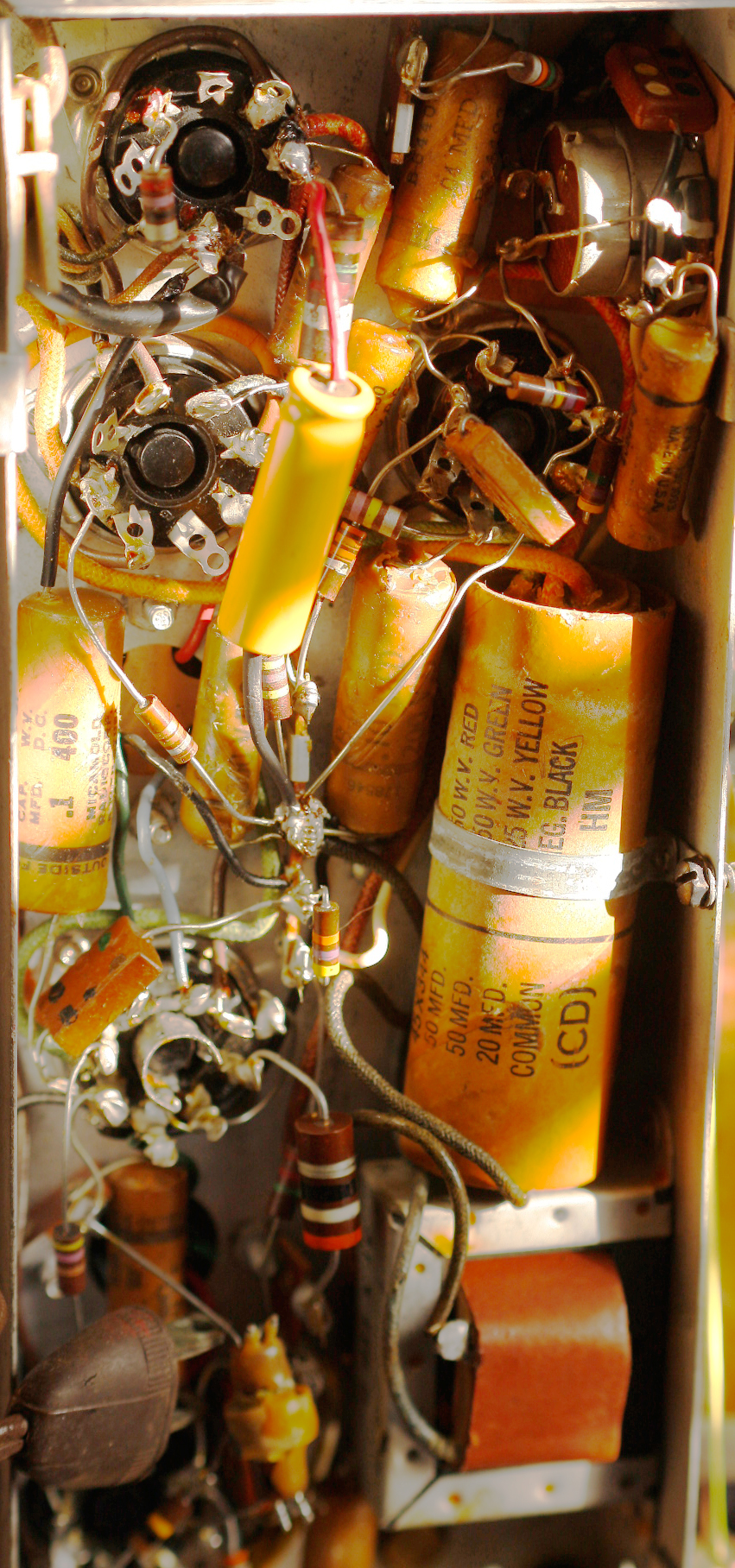 Here's where I'm starting from (left). The filter cap is that big orange cylinder half-way down the right side of the photo. It's a 50µ-50µ-20µF: the 50µFs are 150V, one connected to a red wire, one to a green wire. The 20µF is 25V and has a yellow wire. These three lead out one side of the tube (top on the photo). All share one common (black) lead coming out the bottom. The tube has a metal strap that is screwed to the chassis.
I noted which wire is which (it's not too difficult even with my color-blindness) and snipped them close to the cap. I suppose I should have unsoldered them at the opposite ends but I didn't want to snake them through again when I replaced the cap.
 There's a big yellow cap (the markings are turned away in this photo) on the left side of the photo, about 1/3rd of the way down—it's the size of a piece of chalk. That's the one we tacked in last summer to fix the hum the first time, when it looked like the main filter cap just had one bad section. So this guy is going to have to come out before I'm done.
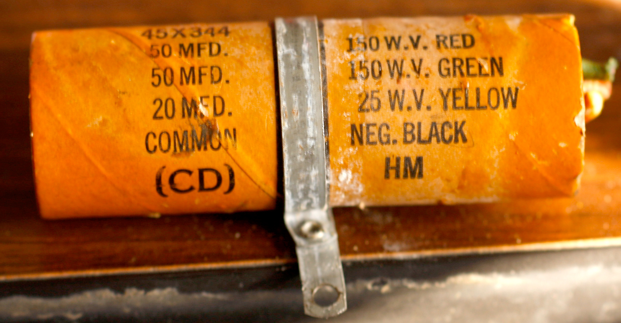
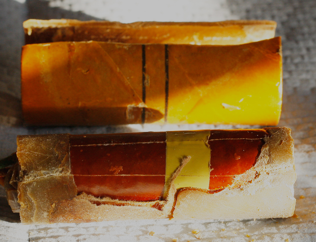
Here's the cap (right) removed. I wanted a good photo in case something went horribly wrong and I would need to Photoshop a replacement paper cover.
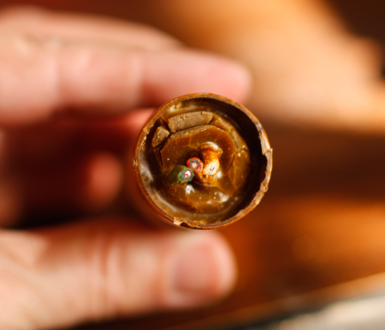 Here are the two ends with leads already snipped. The common side is nice and smooth. The "hot" side looks torn up. Not sure if it was always like this or if it's disintegrating on me. Either way I figure it was time to come out. I've got an idea on how to seal the ends and make it kinda-sorta look the same.
 So I removed the strap, put on my safety glasses (mainly to keep bits of something flicking into my eyes, rather than worrying about an explosion), and sliced it down the back lengthwise using a utility knife. I tried using a straight-edge but couldn't hold it securely, so I ended up with a slightly crooked line but all my fingers intact. Then I (fairly) carefully pealed it open and managed to get the "guts" out of it. (Left)
 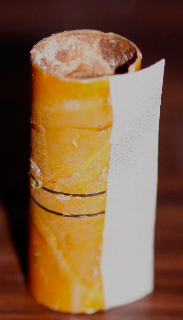 Thought about keeping it, but I believe electrolytics have 18 kinds of toxic crud in them and decided it wasn't worth it. I also washed my hands about a hundred times while I did all this.
So now I have an empty tube. I got a piece of stiff, heavy paper and cut out a piece to use as a backing for the glue. I've tried to glue things seem-to-seem before and it never works. I rolled the paper around a flashlight handle to give it some curl, put some household white glue on half, smeared some on the inside of part of the tube, waited a couple minutes to let them get tacky (things don't slide around that way and stuck it down (right). I gave it awhile to dry and set (it's warm here, even by local standards, so it didn't take long), then did the same to the other half, tucked it in, pressed it together, and done. I used one of those wire-ties to hold it together while it dried. (Left)
Coming soon: making up the new "guts", packing and refitting into the chassis.
So far this has been a comedy of errors. I had ordered a couple 50µF and they had arrived in the mail. At the time I'd ordered 450V versions and hadn't thought anything of it—until I saw how big they were and that I wouldn't be able to fit everything into the tube. I could squeeze the two 50-mikes in (barely) but there'd be no room for the 20µF. I dug through my paltry parts box and came up with a small 50µF @160V, but only one. Some more digging and I finally worked out a deal where I could use the 50 @160V, make up another from a parallel pair of 25µF @160, and another 20µF @ 250, and everything would fit nicely. Back on track!
 That worked for about 5 minutes until I managed to break the cathode lead off the 50µF; the cap is aluminum so I couldn't solder it back. So after much searchng, I ended up placing another order to JustRadios.com and camped out by the mailbox.
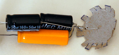
When they arrived, I took the two 50s and a 20 (the long orange one in the photo) and tied all the cathodes together. Then using a bunch of clip leads, I patched it into the radio and tried it out. Worked well with no hum. So I got one thing done at least.
The end caps are from a piece of gray card stock I had laying around. I poked the leads through on each because I knew I'd never manage to do it if I set the cap first and then tried to put the new capacitors in. I left about 1/16" of clearance on each end. I bent a kink onto the 20µ lead to identify it.
 I had scraped/melted off the original wax and kept it, but I only had a little and thought it would never be enough, so I bought a couple of candles at the local crafts store. I bought a burgandy one for the ends and an ivory colored one for the tube. For the ends, I lit the burgandy candle and dripped it until I'd filled the ends. I got some wax on the lead but that was easily cleaned off.
Dripping was slow and tedious and uneven, which didn't matter on the caps but I thought it would matter a lot on the case, so I cut a chunk of the ivory candle off and put in the bowl with the old wax to melt. Microwaving didn't touch it, so I put the bowl on top of a saucepan with boiling water and double-boiled it, the way you'd melt chocolate. That worked. I took a cheap paintbrush and painted the wax on the tube; it came out so-so. The ivory wax dried somewhat opaque; the original wax was clear, so in hindsight I should have just used the original and been done with it. Oh well—next time.
Current status: works fine.