
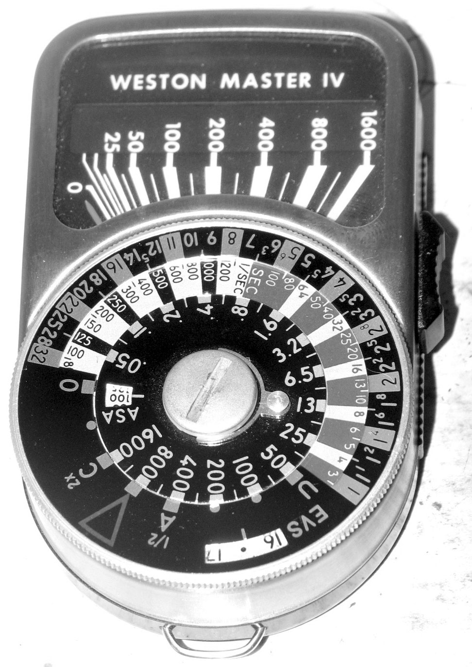
BaselineThis is the unit before we begin. Hopefully it's what we'll get when we're done. Unlike the earlier Masters, disassembly of the Master IV begins at the front. Use a large blade screwdriver and remove that big screw in the center of the calculator dial. The dial itself is a self-contained module, so you don't have to worry about it falling apart and trying to get it synched up properly. Also, unlike other meters from this era, the calculator does NOT connect to a pointer or anything else inside. |
Click on image to see a larger version |
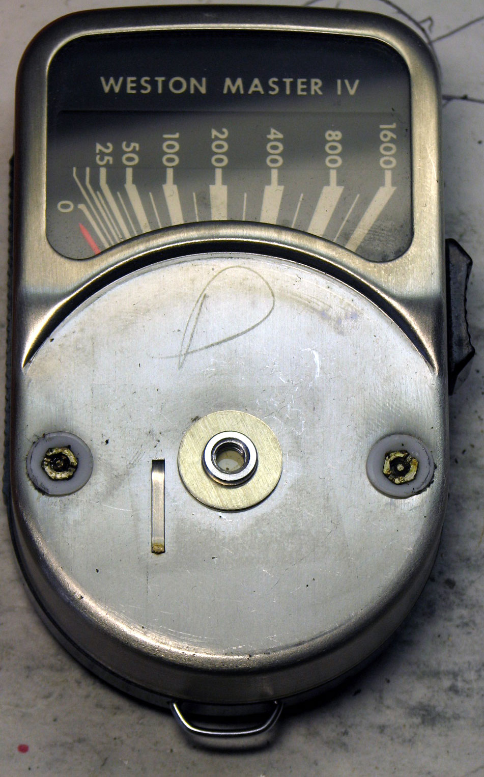
Calculator Dial RemovedNow the tricky part. Weston liked to use tamper-resistant heads to keep people (like me) from getting into the meter. In this case, there are two hex-head nuts (at 3 and 9 o'clock on the cover). They have a slot across the face, but in the middle there's a raised nub so you can't just put a screwdriver on it. You either need very small spanners, strong tweezers, or a tool of your own making. We took an old, straight screwdriver and ground a notch in the center. It fit nicely and removed the heads easily. Set the nut heads and the vinyl washers aside. The vinyl washer tend to stick up and let the calculator dial turn without grinding against the nuts, so don't lose them. The top case of the meter should lift off pretty easily. |
Click on image to see a larger version |
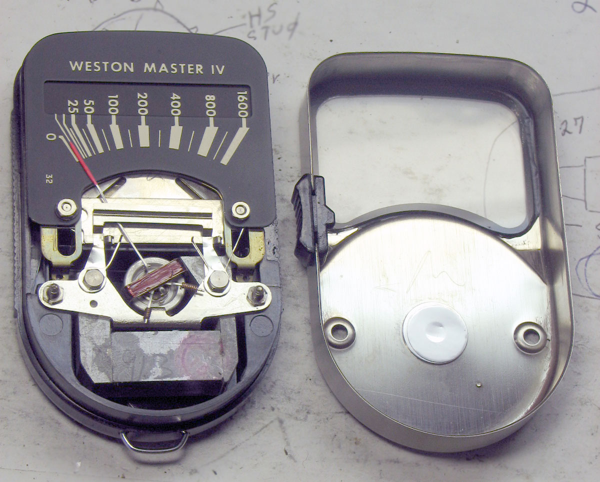
Cover RemovedThe front cover lifts off cleanly, but the pointer lock button on the side will probably fall out. The button a simple slide switch with a nub on it. When the switch is in "lock" position (up toward the meter area), the nub doesn't touch anything. When the switch is in "unlock" position (down toward the calculator dial), the nub pushes a button on the side that raises a bar and allows the needle to swing freely. At rest, the bar normally presses against the needle and holds it in place. The top of the meter has the scale face. This is a double-decker affair, just like earlier models. The lower panel with the scale numbers slides up and down on a track, and it's pushed up and down by springs that are connected to the hinge on the baffle door in the rear of the unit. Unforunately you can't see it well in this photo. The middle of the unit has the meter needle. That bar going across is resting lightly on the needle, keeping it from jumping back and forth. There's a button on the right hand (as you look at it) side just under the dial face (not visible in this photo). If you press it, it'll raise the bar and the needle should able to swing. This is a good first test. Push and hold the button to raise the bar and see if the meter needle can swing. Don't touch the needle. You can blow across it gently and it should swing. If it swings freely, you're lucky. If it's bound up, it'll be infinitely harder (or virtually impossible) fix. I was lucky. The needle swung easily. Unfortunately, when I aimed the cell at the light, the meter still didn't respond. So something's definitely broken. Next we removed that top meter face plate. There are two hex-head screws (not tamper-resistant). I used an Xcelite driver size P-5. |
Click on image to see a larger version |
| Main | Next |