
If you landed here directly from somewhere (like Google), the previous steps are described here.
The Ignition Coil and Harness
Now for the hard part. I say this every time I get to the next step, and it always seem to be true.
The engine electrical system is making my hair fall out. The service manual doesn't really treat the electronics the way that I would like, especially where the wiring harnesses come into play. The harnesses (of which there are many) collect a bundle of wires together and make things relatively neat and tidy. The bad part of them is that it's often difficult to trace wires using them, as they tend to disappear under unsulation and reappear God-knows-where.
As an example of how the service manual deals with things, let's take the ignition coil. Several wires connect to it. The manual tells how to remove and replace it—simply disconnect all the wires and note where they go, and then put them back on the same places during reinstallation. Have to replace a whole harness? There's no mention of that. What to do if some or all of the harness is missing? There's a blank page at the end of the book to cover that.
The service manual does have a master schematic diagram of the wiring, which is a giant pile of spaghetti.
All of the harnesses have part numbers, so you might think the Parts Manual might show you what they look like. You would be wrong. It does show where the harnesses are located:
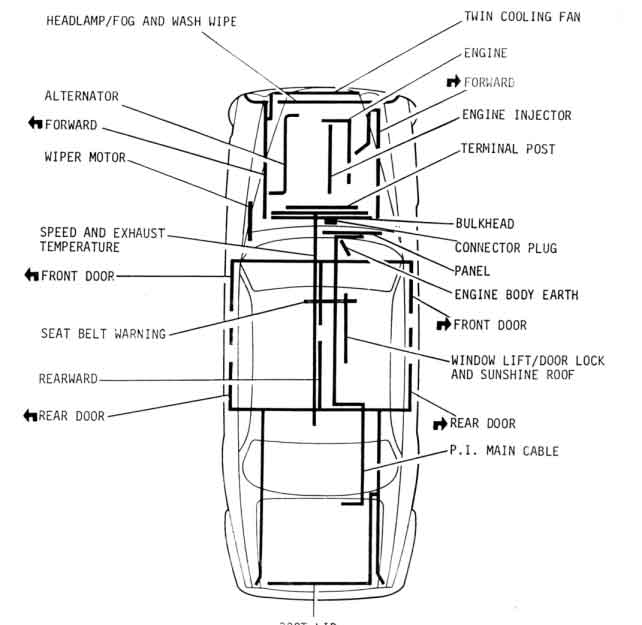
They do list the part numbers of the harnesses, but you can't see what the harnesses actually look like, except in a few of the simple instances—such as the harness for the glove box.
Why do you need to see a harness? Because if you take one of the more elaborate ones, like the Engine harness, there are a number of wires on both ends in addition to the plugs. All of these wires have to plug into something, but it's not always apparent where they go.
So finally there's the Electrical Manual, S-57. My copy is in a 3-ring binder. On the one hand, it is a much better, more thorough treatment of the electrical system. There are a number of schematics and each one only covers a particular circuit or group, rather than lumping them all together into a single mess. But again, wiring harnesses don't get mentioned.
They tell you want the color coding on the wires mean, which is nice, but not always as useful as one might hope, and for three reasons.
-
in my case I'm somewhat color blind. I can tell yellow from blue and so on, but I need the color to be strong and fairly large to see it. On little wires, or stripes along wires, black and brown and gray all look identical to me. Red and brown often look the same, and there are other head scratchers. Another of my hobbies is electronics and I have the same problem reading the bands on resistors. The difference there is that I can pull out an ohmmeter and read the value. There's no real equivalent here.
-
my engine is filthy, and while that's partly my fault, engines collect dirt and grime no matter what; the wires, especially a bundle of wires, tend to collect grease and dirt and they're not that easy to clean. The result makes the color reading that much more difficult.
-
because the harnesses can be long and branch out like a vine, they may tuck in, around and be pushed through things, making wires difficult to trace. So if you see a blue wire on one end of the harness, it can be difficult to find the other end of it.
A diagram of the harness (at least for the most elaborate ones), with a callout of where each wire goes on each end, would go a long way toward simplifying the electrical system on the car.
Why I'm complaining about all this will become clear in a moment.
So what happened is this. There is a big bundle of wires that run along the water-rail on the intake side of the head, and another bunch of wires that plug into the ignition coil. The rear of the engine is easy: there are two big plugs and one small plug that connect those wires to other harnesses elsewhere in the car. Easy.
The radiator end isn't so easy. It turns out that there are two harnesses here. One is a big brute called the Fuel Injector Harness. It plugs into all of the fuel injectors, the Extra Air Injector Switch, and a couple of other things on the water rail.
There's also the Engine Harness. This hooks up to the ignition coil, a couple of other items on the water rail, and it plugs into the Right Hand Forward Harness. Easy—right?
Not so much. Because it also plugs into a couple other things on the right fender side, and it sends another branch across the front of the engine, right where the head and the block meet, and hooks up to the Air Conditioner Compressor and maybe the alternator (I haven't figured this out yet).
There's a third harness that I haven't seen identified anywhere in any of the books. This one starts at the rear of the engine on the intake side, back at the same location where the fuel injector harness plugs in. It goes along the water rail and plugs into what I believe is the Water Temperature Sender (it's on the back end of the water rail), then has a pair of plugs that drop down through the rail and hook up to the Purge Valve Switch which is on the inside fender wall, and snakes around the front of the engine to the exhaust side, where it plugs onto the Air Switching Valve that's located on the back of the air pump. I've found very few mentions of this harness, one guy on a Jaguar forum called it an emissions harness, but no part number. My own request for the name and part number of come up empty. I'm going to call it the Smog Harness.
One of the problems with this arrangement is that even though the wires were meant to withstand heat, they still get baked over time. Assuming my harnesses are original, they were wired over 30 years ago. The engine harness, in particular the portion that goes across the front of the engine, is stiff and brittle. It's like handing little branches on a long-dead tree. They don't bend anymore, they snap.
When I took the wires off the old the head, I labelled them all. But when I put the new head on, it turned out I got another Engine Harness that was already on it. So now I had part of the "new" harness on the new head, and my old harness that was connected to other stuff. Should be easy to remove the old harness and just plug in the new one, right?
Well, no. A couple of the tags fell off the old harness as it disintegrated, but worse—the "new" harness was snipped in a few places. The big plug that connects to the RH Forward harness is there, but a lot of the branch wires are a mystery. Even if I can (and I probably could) identify all the snipped wires, I'm missing the part that goes across the front of the engine. I'd have to splice it onto the old harness, and those fried wires aren't going to cooperate.
I purchased a new Engine Harness from British-Wiring, and it's in the mail as I type this. Since I can't source a replacement Smog Harness, I'm going to rebuild mine.
Rebuilding the Smog Harness / Emissions Harness
As I complained about above, the harness wires were largely dry and brittle. I checked continuity on all the plug ends to see what connected to what, and found one of the connections was broken inside. So I pulled off much of the electrical tape and saw a lot of inline crimp connectors. I cut out the one where the wire was broken and soldered in a wire to replace it. But the more I looked at it, the less confidence I had in the rest of the harness. I figured it would break again as I tried to put it back on the engine. So I'm going to snip all the wires an inch or so behind the connectors and replace the old wire with new, 14 guage stranded hookup wire. I'm going to solder all connections and use shrink wrap for a little more mechanical strength, and cover it in flexible sleeving for a little thermal protection and also to make it look decent.
Somewhere I read someone expressed a concern about solder melting, but it seems to me that if the engine compartment gets hot enough to melt the solder (around 370 °F), I'm going to have other problems first.
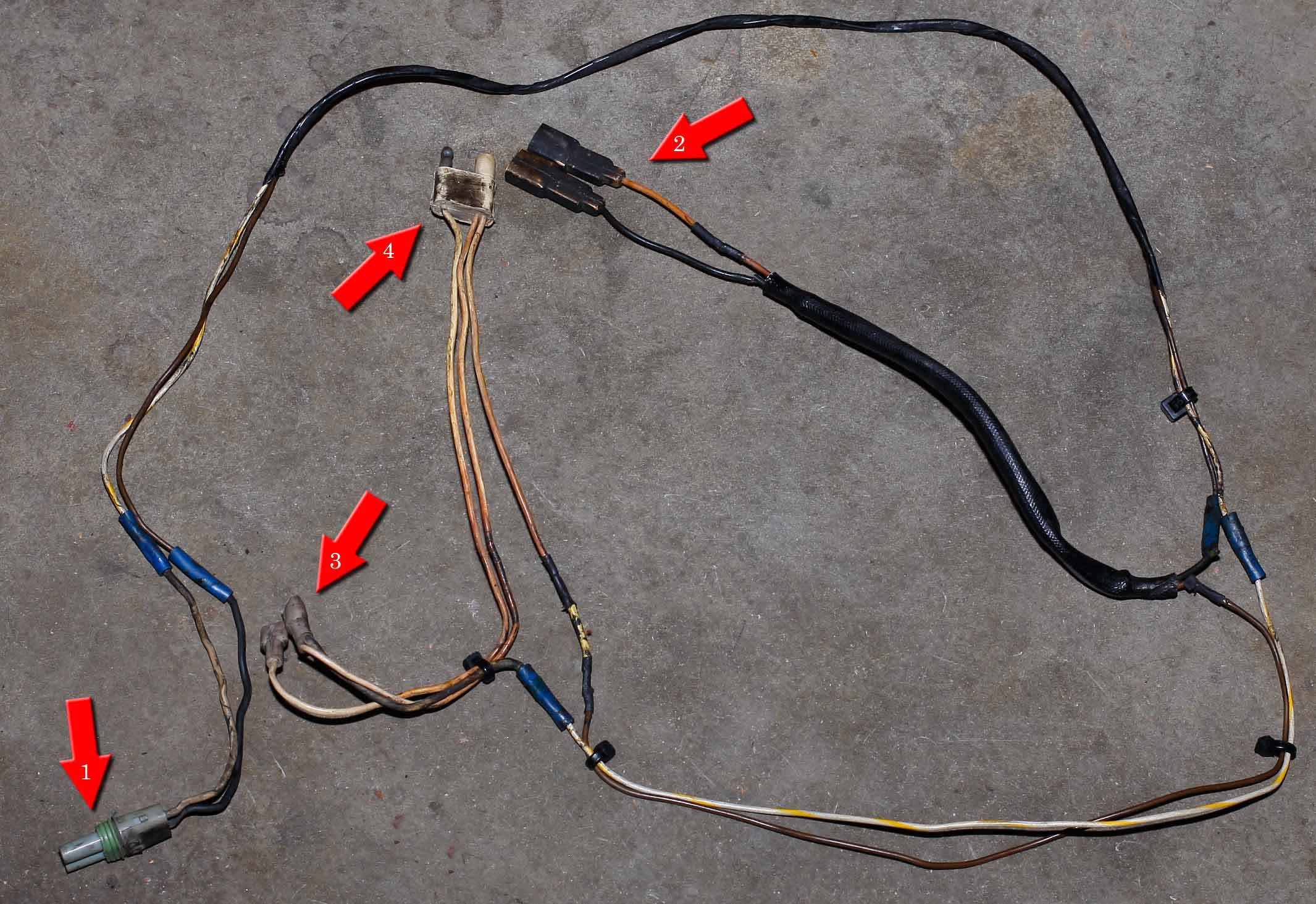
Click on the picture for the full-size image. I numbered the connectors in order of hook-ups.
This goes into the Air Switching Valve on the back of the Air Pump (exhaust side).
-
These tuck down below the front of the water rail, just in front of the Ignition Coil, where they hook up to the Purge Valve Switch
-
These hook up to the Thermal Switch, which is located at the rear of the water rail.
-
This goes to the plug behind the rear end of the water rail, next to the plugs where the Fuel Injector Harness plugs are located.
Here's the harness after I worked it over. I replaced the long lengths of wire but left about an inch or so from the connectors. The black woven stuff is relatively high temperature sleeving (melts around 350°F), which I found at Fry's Electronics of all places. I'm continually amazed at what Fry's does and does not have.
The electrical tape is Scotch 700. It's rated to 194 °F so it may turn into a mess. We'll see. But at the moment it's the best I've got, and it's still better than the other electrical tapes I have. 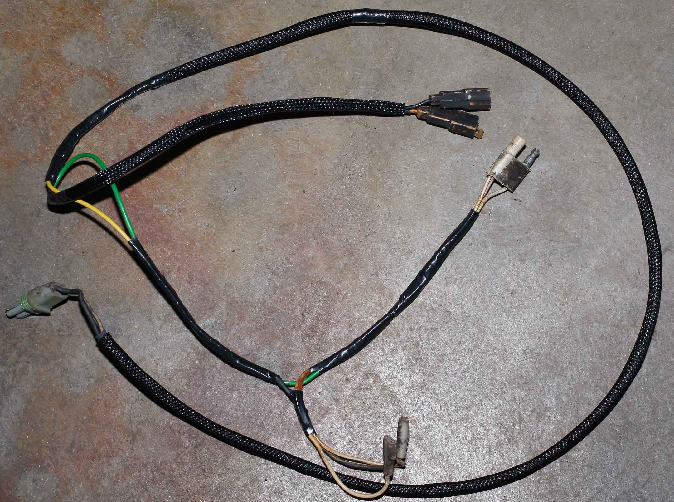
All in all, not bad for my first attempt at making a harness. All the connections work, which is better than where I started.
The Engine Harness
I got the engine harness from British Wiring.com. I was going to photograph it but I a) forgot and b) couldn't do any better than the one on their website.
I worked from the bottom up. The big plug goes into the RH Forward harness plug, which is down near the bottom of the interior fender wall. There's a single wire barrel plug that also mates up in the same location. Travelling up a bit, there's a green wire that goes to the oil pressure switch, which is mounted in the bottom of the block. There's also a much longer white-with-red-stripe wire. I had a tough time with this one, but finally found that it goes way back along the bottom of the engine and connects to the top of the oil pressure sender, which is a bulb located behind the motor oil filter.
Going upward, the wire then branches into two major arteries. One goes up to the water rail and back toward the coil. For the ignition coil wires, the plain white one goes to the + terminal, the other white striped wires go to the negative terminal. The blue-green (whatever color it's supposed to be) goes to the water temp sender (I believe that's what it is), located just behind the ignition coil. It's easy because there's only one connector. The final two wire pair goes back to the end of the rail and connects to what I believe is the water temperature sensor.
The other artery goes across the front of the engine, right about where the head and the block meet, and then tucks down to connect up the A/C compressor and the Alternator. The long red wire goes farthest down and connects to the bottom of the alternator. I had to get under the car and behind the alternator to see it, and even then I still had a tough time getting to it (but managed).
The A/C compressor isn't quite so bad. The original one looped underneath the compressor; the ring goes under a bolt in the bottom bracket, and the two plugs come up to the side of the compressor that's fairly easy to get to. Either my harness was too short or I didn't route it correctly, so I ran it in over the top of the compressor (sandwiched between the compressor and the Air Pump) and put the ring under another bolt. The other two wires plugged in normally.
Mop Up
After that there wasn't much left. Making sure there were no loose ends on the exhaust side. On the Intake side, I put the distributor cap back on, the plug wires back on, the air cleaner on, and the battery back in. Put a gallon of gas split between the tanks.
Sat down and put the key in. Turned it to Accessory. No pops, no bangs, no smoke. Turned it to ON. No pops, no smoke, no bangs. The car fired up (after some fuss) on three cylinders. Replaced two injectors and failed a compression test on #5. A stuck/bent/somehow-or-other-wonky intake valve.
And I got to do it all over again. . . .