
All this for that:
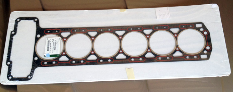
The head is back on. No photos since it looked very much like taking the head off in reverse. Going back on did take some effort. I put copper (copper is high-temperature) anti-seize goop on all of the studs and a little on the holes, hoping it would act as lubricant as well as a protectant and motor oil on the timing chains. It still turned out to be a two man job: one to run the hoist and the other to adjust the head as it went down. I tried doing it solo but it was like everything was made of velcro.
Got the head down, bolted and torqued. Got the exhaust reconnected. The book (Jaguar factory shop manual) says to bolt everything on loosely and fuss with it until everything fits nicely, and that turns out to be correct. It took a lot of jiggling and maneuvering, tightening and loosening, I got it hooked up.
Cams and Timing Chain Tensioning
Next up was hooking up the camshafts to the timing chain. There are four screws on each, but you can only see two (maybe three if you're lucky) at any time. So you have to bolt two on each, then rotate the engine to bring up the other two to bolt in.
I got two on the exhaust side, but I can only get one on the intake side. The other hole just does not quite match up. I figured I'd slacken the chain a little, put the bolt in, and then tighten the chain back up. Didn't think this would be a big deal. I'd bought the tensioner tool just in case.
In order to explain this, here are the diagrams from the factory parts book (I erased parts that are not relevant to this):
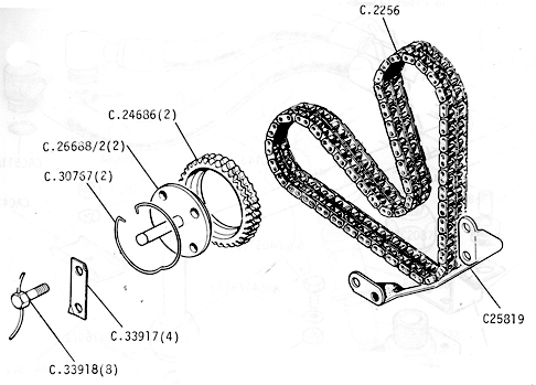
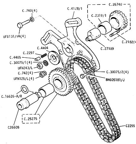
What happens is that Idler Sprocket (C.26740 - upper right on the second diagram) is the gear that sits in the bottom of the V that the upper timing chain makes. The sprocket spins, but in the middle there's a piece called the Idler Eccentric Shaft (C.27189), which has a neck that's off-center. The neck sticks throught that big Bracket (C.4128/1). On the other side of that bracket, there's an Adjuster Plate (C.4404) that fits onto the Eccentric Shaft. The Shaft is keyed and the Plate has a keyway so it can only go on one way. There are two holes drilled into the Plate, so you can fit a spanner wrench into it and turn it. When the Eccentric Shaft is down (as it is in the diagram), the Sprocket is up and you get the least tension on the chain. When the Shaft is up, the Sprocket is down and you get the most tension on the chain.
The Adjuster Plate is held in place by a lock washer and a nut (C.30075/1(4) and UFN243/L). On older versions of the XK engine, I'm told, this is enough. But somewhere along the line, Jaguar decided to add a failsafe.
The Plate has teeth around the outer edge. There's a Plunger Pin (C.4405) that also has teeth. The Pin is spring-loaded and fits into the Plate. The teeth in the Pin mesh with the teeth in the gear to keep it from turning. So when you want to change the change the chain tension, you loosen the nut, push the Pin, and then use the tool to turn the Adjuster Plate, which turns the Eccentric Shaft. Easy.
In my case, the Pin was stuck. No amount of push would do it. Penetrating oil didn't help. Acetone didn't help. Tapping on it lightly didn't help. Tapping on it with a heavier hammer didn't help. I could have heated it with a torch but I'm always worried I'll set fire to something.
I took the nut and the washer off, took the Plate off, and the Pin still wouldn't come out. I realize now that the Pin was already pushed all the way in&mdashthat the teeth are in the rear of the Pin, not at the front. Still, since I got this far and the Pin was stuck in, I pulled it out with a wrench.
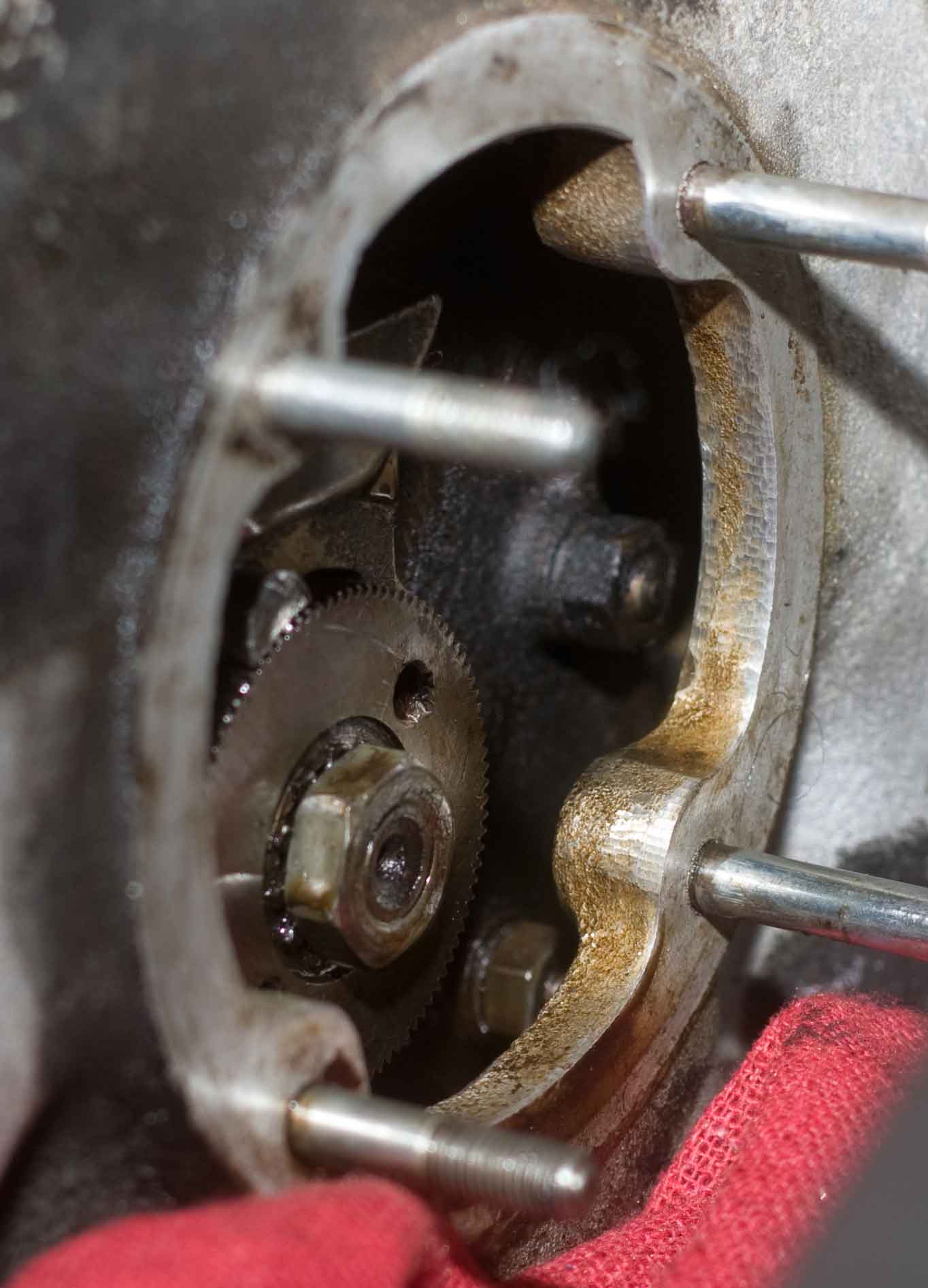
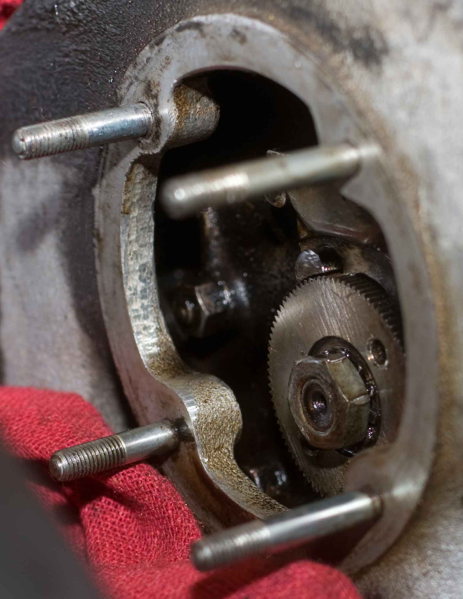
Two shots of the adjusting Plate in place.You can see the Pin at about the 11 o'clock position.
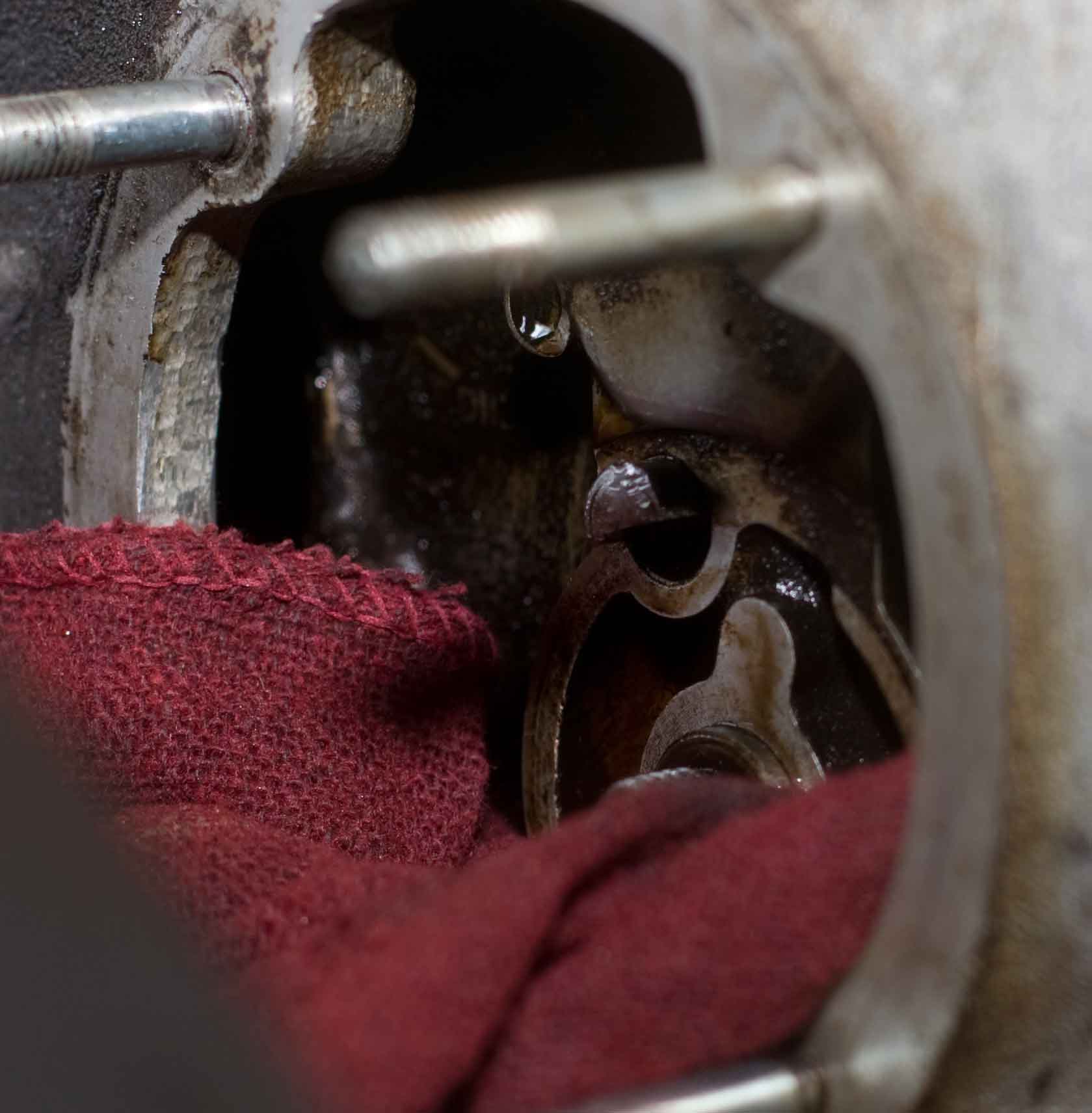
Same thing but with the adjusting Plate removed. The Pin is still in place. Sorry about the rag but I am paranoid of things following down into the engine guts.
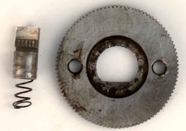
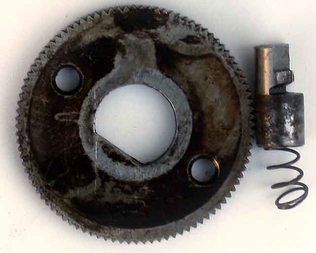
The adjuster Plate and the Pin. The upper photo shows the outside of the Plate (visible when installed); the lower shows the rear of the Plate. If you look at the photo where the Plate is removed, you can see where it presses against the inside of the Plate (it's the relatively clean part).
I took two photos of the Pin to show where the teeth are.
I cleaned up the Pin and the hole (or thought I did), pushed the Pin in, put the adjuster back in, and tried to turn it with the tool. No go. The spring on the Pin is strong and kept pushing everything out. I finally left the Pin out and put the adjuster back on and tried again with the tool. No go. Like the Pin, it's stuck nice and tight.
That's where I am at the moment&mdashstuck. I'm either going to have to spray something in to loosen things up, or re-engineer the tool to give me more torque to turn.
Something's definitely sticky. I'd cleaned the Pin and put it back in, coated with motor oil. It pushed in nice. I put the Plate on and the nut. Couldn't loosen the tension. I left everything in place for 10, maybe 15 minutes. Came back and I couldn't push the Pin in again. It was like it was jammed solid. Very frustrating.
Ultimately the answer was getting a box-end wrench, putting the loop one one of the handles of the tensioner tool, and using the extra leverage to turn it and get it off. Once I did that, I was able to get it off. Later on when I had to put everything back together and set the tension again, I had to use the wrench again to give me enough leverage to turn it. The book says "not to use"undue force." I don't know what they think due force is.
With the tensioner off, I was able to put the bolts back on the accessible part of the cam shafts, cranked the engine around and bolted the others, then brought the engine around to TDC (using the cam alignment tool) and tightened the timing chain. Then it was a matter of putting on the cam covers (with new gaskets) and the engine breather cover.
I stayed on the exhaust side and put on the exhaust manifold heat shield, then the air pump. All this was a fair amount of work but relatively simple in terms of hookups, since there aren't that many loose ends and it was failry obvious what-went-where.
Bolted the radiator back in and hooked up hoses. The top rubber strip that seals against the hood is shot. I'll leave that for later on.
Vacuum Hoses
Back to the intake side, a matter of hooking up what seems like 100 hoses. Colin Chapman said "simplify, then add lightness." Someone in charge at Jaguar looked at this and said, "add more hoses."
Most of the connections were fairly easy because they tended to be either large or small. The large hoses' length and postion tended to show where they went, since there was nowhere else they could logically go. Photos I'd taken during disassembly also helped when it came to hooking up to the pipes that cross from the exhaust to the intake side of the engine.
Where things went sideways was with the small, very flexible hoses, which were long and could theoretically go anywhere.
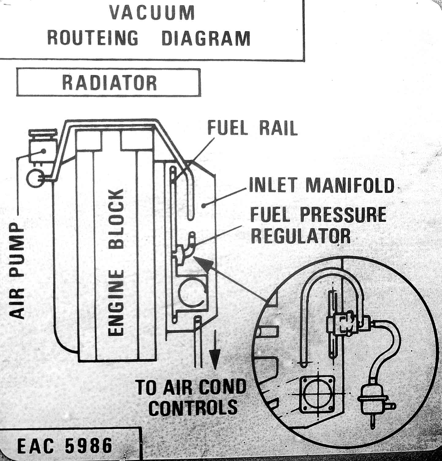
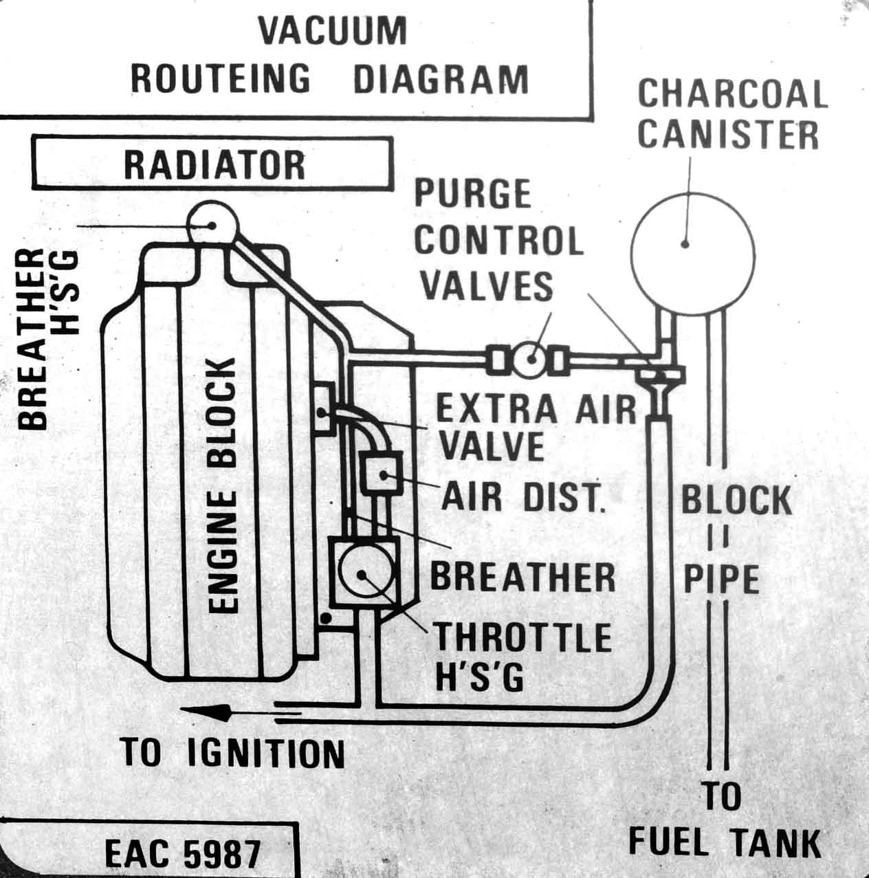
Vacuum lines aren't discussed much in the shop manual. The parts manual helps a little but not enough. Mostly it boils down to three stickers inside of the hood of the car. Click on each to see them larger:
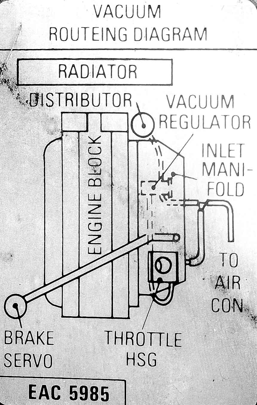
For my purposes, it's covered by EAC-5985 (far left). The problem is that the diagram isn't as clear as I would like.
Actually the problem was that I ended up two sets of hoses, one from the old manifold that came with the car, and another set that came with the new engine. I thought I had tagged everything on the old hose when I disconnected it, but I missed some pieces, the tags fell off, or things were pulled off and I didn't notice. Either way, I had a mess.
There was also the problem that I had some connections and did not know what they were called. A perfect example is the teat (for lack of a better word) on the underside of intake manifold. The teat is broken off in the photo here, but that's where it's located. A small, flexible hose plugs into it. ![]()
There's another small teat on the big tank itself, in the very upper-left corner, but it's capped off. I've got two of these things and they're both capped. It must be a vestigial connection for an earlier configuration.
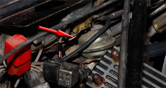
There's a connection on the side of the throttle body for a hose and a connection for a hose coming out of the distributor. I also had a hose behind the battery tray that snakes along the firewall and connects to the vacuum tank, which is a pancake sized/shaped thing on the left-hand fenderwall, tucked behind that great big brake booster. And there's a hose on the right fender wheel-well that snakes through a hole to the evac cannister.
In the middle of all of that, there is this: the vacuum pressure regulator. 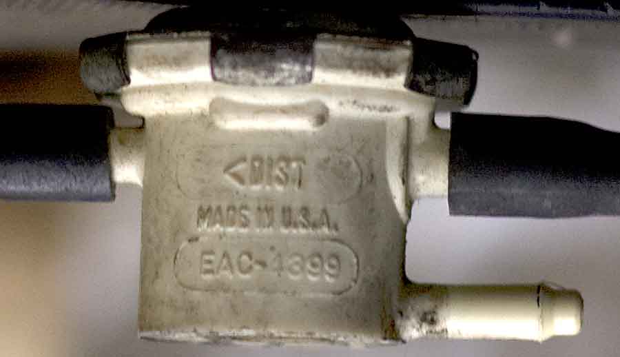
There are three connectors on it. On the side where there's only one connection, that's the Distributor. You run a hose from it to the distributor connector. Easy.
On the side with two connectors, the bottom one says that goes to CARB. The upper one says DELAY.
Now it gets complicated. Ultimately, I ended up with this diagram:
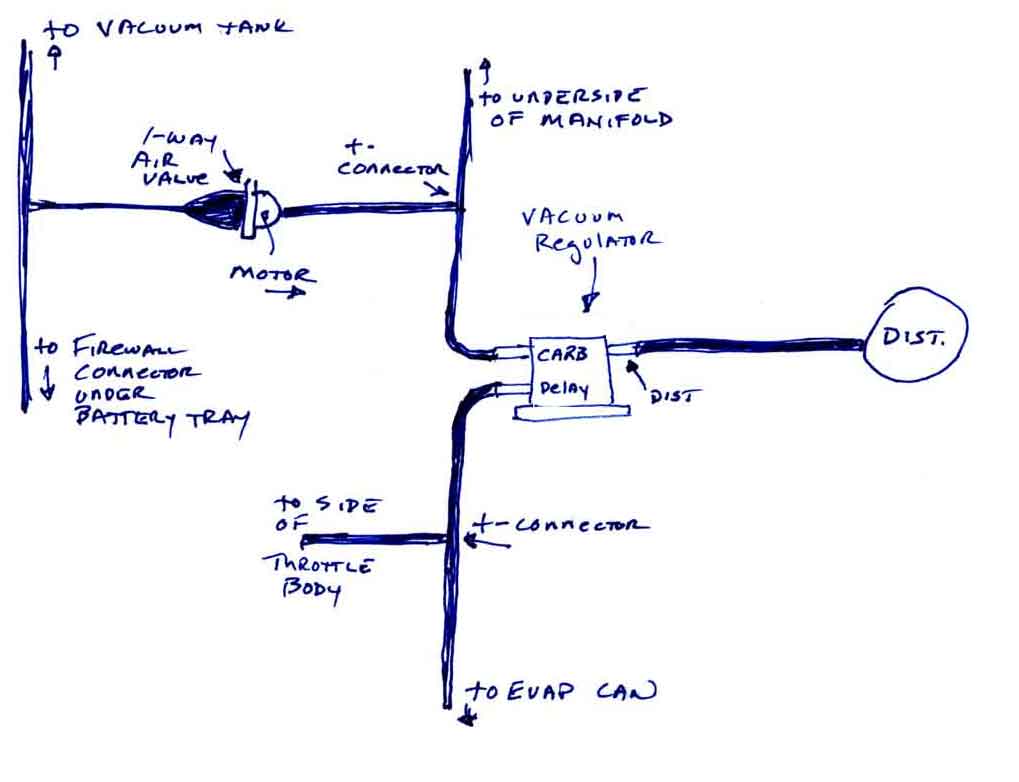
The one-way air valve (not photographed) is a check-valve. One one side it says "motor" and has an arrow pointing outward, which is your direction of airflow. You want to pull a vacuum in the vacuum tank, so the valve only allows air to flow from the vacuum tank to the manifold and the regulator.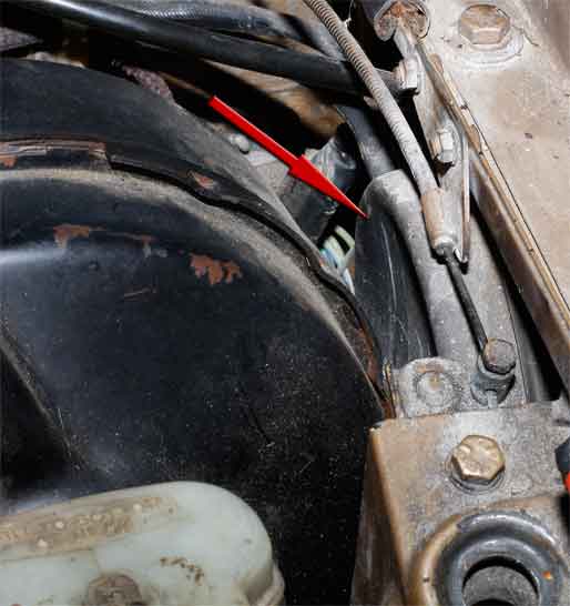
The "Firewall Connector under Battery Tray" was too difficult to photograph. If you are standing at the fender and looking down on the battery tray, the upper left corner of the tray is against the firewall, and the upper right corner is toward the engine. Below the upper right corner there are two connectors on the firewall that go to the cabin A/C. The upper connector's hose goes to the T-connector in my diagram. The lower hose goes up and connects to the heater regulator. The heater regulator is a door-knob looking thing in the center of the firewall just under the cowl, with water hoses connecting underneath.
That's it for the vacuum hoses. All the plumbing is hooked up. Next up is the electrical. And since this is getting very long, we'll continue here.