
Intake Manifold Side
I took the air cleaner off the front end of the MAF (the black box with the yellow writing on it in the photo below). I stuffed a rag in it to keep things from crawling in.
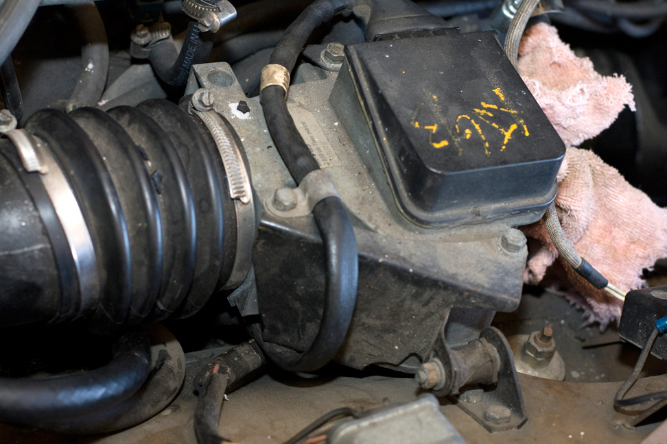 On the top of the MAF unit you can see a heavy cable plugged into it. I removed that, unbolted it from the fender, and took off the hose clamp connecting that huge plenum hose to the throttle body.
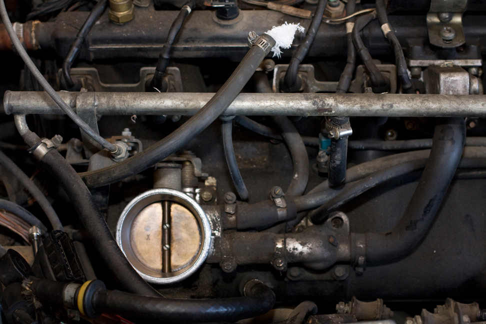
That's the throttle body (lower center). Lots of hoses. Much easier to see now that the MAF and the air cleaner are gone. Any of the hoses that connect to other points on the head can stay, but anything else has to be disconnected.
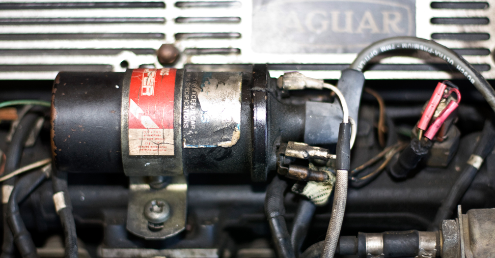
The ignition coil (the big cylinder) looks simple until you realize how many wires go to it. The easy one is the big rubber one in the center—that goes to the center of the distributor cap. The other five all have the same type of connectors and can be put back in the wrong places. I made labels with numbers and tried to match everything up.
After that it was just taking the screw out of the backet (lower left-center), which was suprisingly difficult because the head is nearly stripped. My phillips-head screwdrivers were either too big or too small and all I was doing was making it worse. I ended up at the hardware store and got (if I remember correctly) a #4 Phillips head bit. That was an adventure because even though large Phillips heads are sized from #1 to #5 (in increasing size), most places stop at #3; even kits only include #1 through #3. The professional hardware store had #4, but not #5. I lucked out—#4 did it.
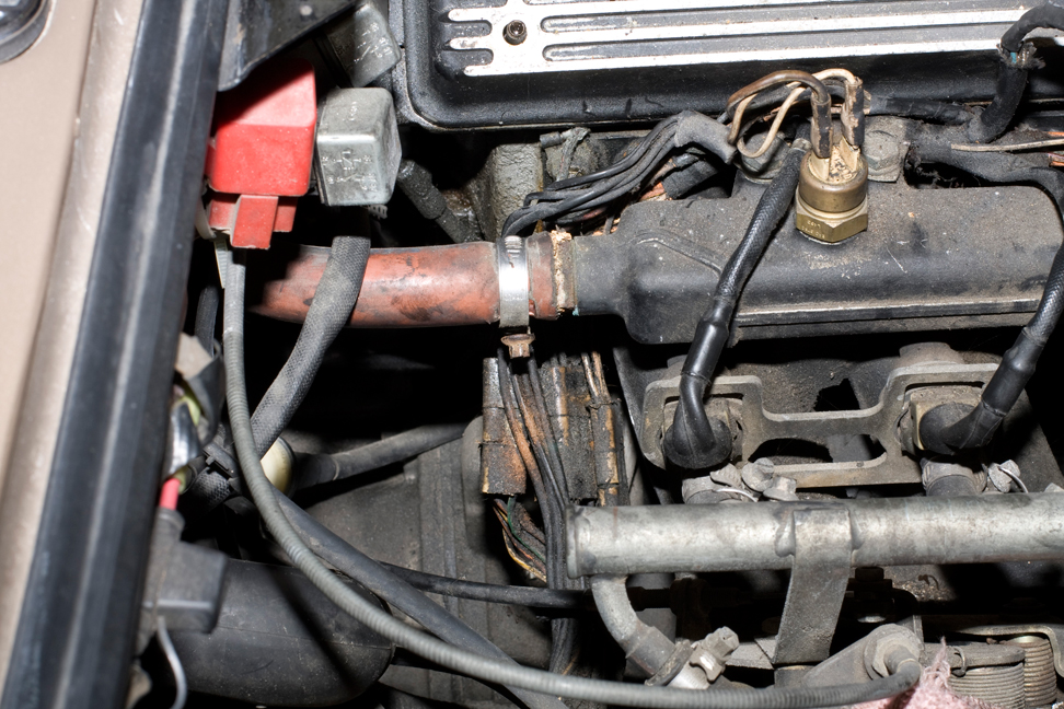
Here's the firewall-end of the intake manifold. That big red hose will have to come off. Going behind it you can see a bunch of grimy wires that are thankfully terminated in big sockets. Those have to be unplugged.
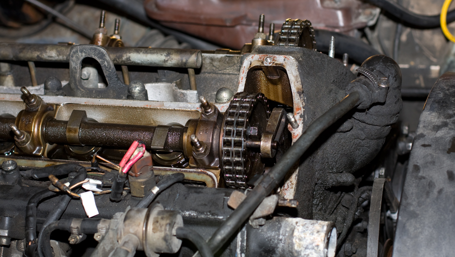
Here the intake-side cam cover is removed. The mound of grease and grime on the far left is the breather cover. Normally I'd leave it on because it's part of the head, but I'll be taking it off because I want to use the mounting studs later.
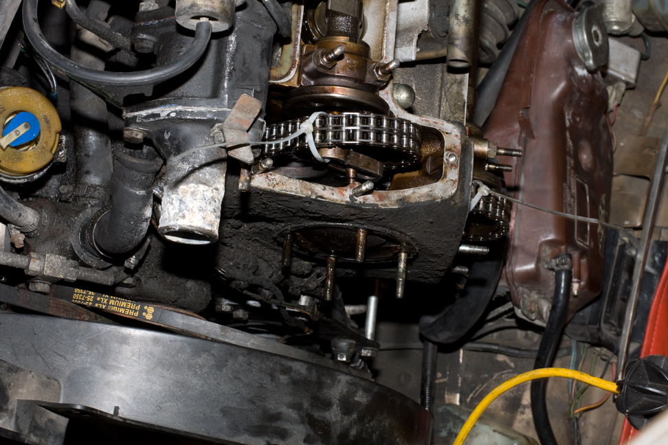
Another view (sideways), but this time with the breather removed and the studs exposed. Also, the timing chain has been unbolted from the camshafts and locked into place by zip ties.
Before this (no photos), I had removed the radiator so I could put a socket on the harmonic balancer and cranked the engine around to TDC. If the timing chains stay put and I don't rotate the engine, everything should remain in Time when I put it back together.
All the connections (I think) are off. Now it's time to bring in the engine hoist and pull.