
Schematic symbols for tubes are varied and complicated, and they changed over the years. This a brief overview of what they look like at various points in time and what they mean.
Note 1: tube symbols are not mandated by law—they're conventions followed by the engineers and draftsmen who make them. When I say something was from a particular period, say the early 1930s, it simply means that it was most common at that time. Tube symbol conventions from the early 1930s were still being used in the 1950s, albiet rarely.
Note 2: almost all images can be clicked on to show a larger version.
The 1920s
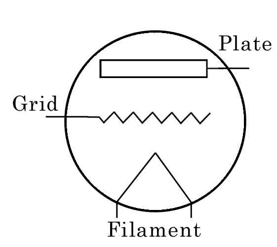
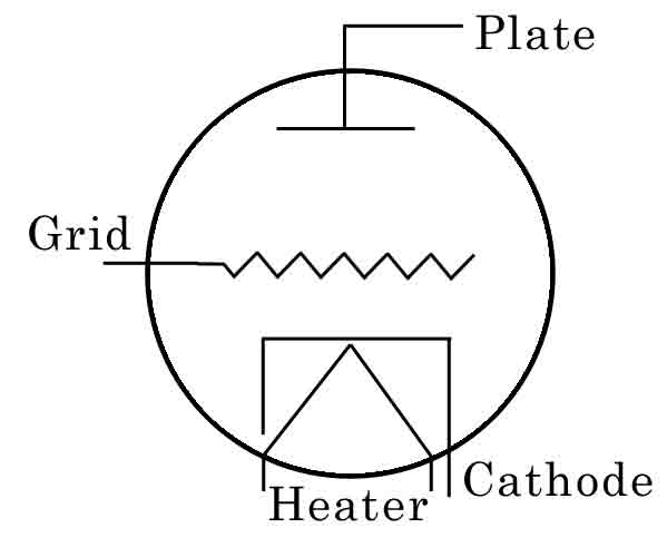
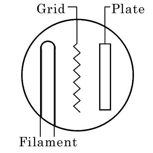 The earliest tube symbols started with pictorial elements that are depictions of what the actual elements looked like. The shell was a circle, the filament was a tall loop, the plate really was a plate, and the control grid was a wire in between them. Supposedly, the man who made DeForest's first three-element tube bent the electrode in this zig-zag fashion to increase the surface area.
Loop filaments (left) are common into the early to mid-20s, but they quickly change over to the inverted-V style (right), and remain that way to this day.
 These tube elements are ordered horizontally with electron flow from right to left. Later on, this would be changed to a horizontal arrangement with the filament on the bottom and the plate on top (except on occasions where it was useful to rotate the elements to symplify the diagram).
Another somewhat-common variation from that era is simply not drawing the shell. The problem with this is the grid symbol looks just like a resistor, though it's only connected on one end, and the tubes tended to disappear in the diagrams. Drawing circles around the tube elements drew them easily to attention, and it made the grid symbol obvious and different from resistors.
The 1930s
The 1930s brought out a big difference, as the symbols rapidly changed to what we know today.
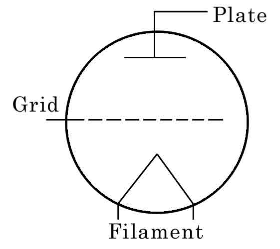
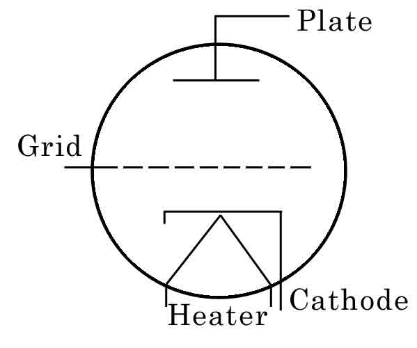
First, the elements were rotated so that electron flow went from the bottom up: the filament was the bottom, then the cathode (if it had one), then the plate at the top. Grids appeared in-between the cathode and plate in the same order they would in the actual tube (i.e. control grid closest to the cathode, supressor closest to the plate).
Next, the plate was changed from a rectangle with a lead into an inverted T. When cathodes began to appear, the early symbols despicted a square or rectangle that nearly enclosed the filament (now called a heater), but quickly changed to become more of an inverted L, with just a vestigial stub on the far end.
The grid was changed from a zig-zag to a dashed line. This may have been to make the drawing a little less busy and easier to read. Early tubes only had one grid, but by the 30s, three grids were common and five grids were beginning to appear, and all those zig-zags looked like a mess. Making dashed lines cleaned up the interior a bit; plus it further distanced the grid from being mistaken for a resistor.
The zig-zag grid was one of the elements most stubbornly clung to, and appears in drawings long after the new style had been widely adopted.
Octals and Loktals
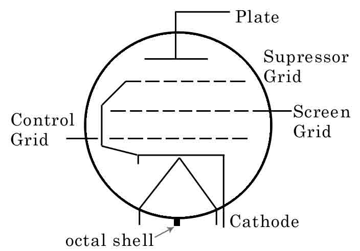
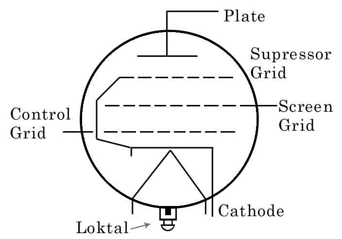
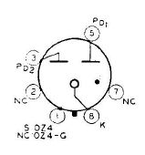
Octals and Loktals appeared in the mid-to-late 30s. Octals are identified by having a little black box at the 6 o'clock position on the shell; Loktals got a little more elaborate diagram to show the "locking" pin. As far as I can tell, no other basing type (e.g. 7- or 9-pin miniature tubes) have a special basing symbol.
Diagram Conventions
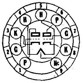
Pin numbers on schematic diagrams are almost always displayed in the order that works best for the diagram; the number appears next to the lead of the element being connected. In the case of the pentode to the left, this is a metal-shell octal tube, so Pin 1 is the shell. Pins 2 and 7 are the heater. Pin 4 is the control grid, Pin 5 is the screen. The supressor is internally connected to the cathode. Pin 8 is the cathode. Pin 6 is not used.
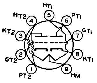
While most schematics number the pins on whatever order makes the diagram easiest to read, a few schematics will force the diagram to follow the actual tube pin layout. The image above right (labelled 12SJ7) is from a schematic that uses this convention. The pins aren't numbered, but they're identified in the order they are found on the base (metal shell, heater, supressor, control grid, cathode, screen, heater, plate). The wiring diagram both inside and outside the tube has numerous overlaps to accommodate it. You don't see this much, but they do show up occasionally.
 In the late 30s and 40s, as designs and schematics got ever more complicated, the heater connections were often elminated as a way of reducing the number of lines on the drawing. One way to do that was to put a mark, often an X, for the fliaments. On the power transfomer's secondary winding that powered the tubes, two corresponding Xs would appear; the X's were the diagram connection between the power supply and the tube's heaters. Another common version shows an X or an arrow on one side of the heater, and a ground symbol on the other.
A more common version, particularly in the 40s and 50s, was to elminate the heater entirely whenever possible and show the filament connections down by the power supply. Since tube heaters were usually on their own separate circuit, this made sense, and it simplified the diagrams once you got used to seeing it that way.
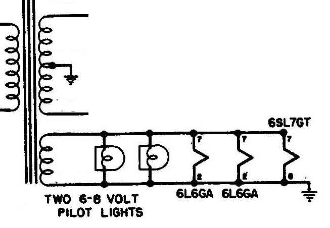
The image at the upper left shows the heater string connected to a transformer, where all the 6-volt tubes are connected in-parallel. Specific tubes are called out, and their pin connections are called. Note that the schematic has been edited to remove distracting components.
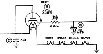
The image at the lower left is similar, but is from an All-American 5 layout where the heaters are connected in-series. Again, specific tubes are called out and their pin connections noted.
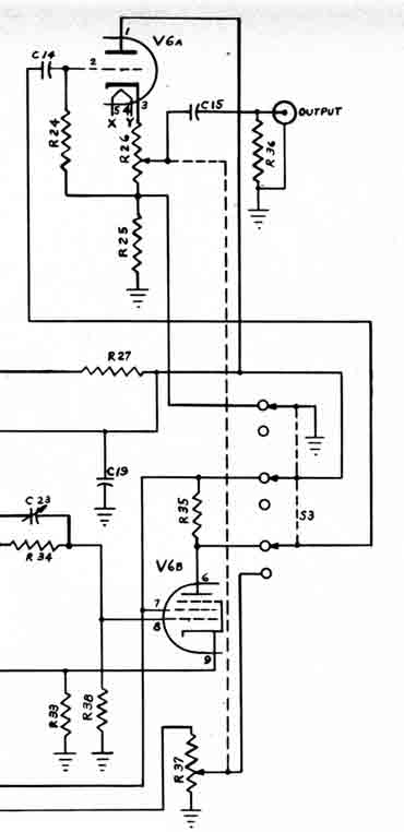 The last convention I want to show is commonly seen on test equipment circuits, where a "twin triode" tube (e.g. a 12AU7) is shown split in half, with one half on one side of the schematic and the other half elsewhere. Twin-triodes are perfect for this sort of thing because they're really two triodes in a single shell, and they can operate independently; but the example below (and illustrated on the right) is actually a 6AN8: a combination triode and pentode.
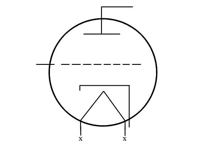
The schematic to the right (click on it to make it larger) shows a tube designated "V6" as split in half: V6A is at the top, and is connected as follows: the plate is Pin 1, the grid is Pin 2, the cathode is Pin 3, and the filaments are Pins 4 and 5. V6B (at the bottom) has the plate at Pin 6, a screen on Pin 7, the control grid on Pin 8, and the cathode on Pin 9.
The heater (Pins 4 and 5) is common to both halves so it's only shown once. There's an additional "X" and "Y" marked on them, and they correspond to an "X" and "Y" on the power supply section (not shown here).
[In case anyone cares, that's a Jackson 605 Sine- and Square-Wave Generator.]
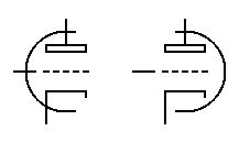
RCA vs. Sylvania Tube Manual Diagrams
These are diagrams of the same tube (12AX7): the left side comes from an RCA manual; the right side comes from a Sylvania manual (both from the 1950s). Both are very similar: because they're from a tube manual, not in actual use in a schematic, the pins are counted in order in a clockwise fashion, as they would appear on the tube base. In order to accomodate that, the internal leads are a bit convoluted and messy. RCA's uses a scheme that's very close to the actual schematic diagram. Sylvania uses something of their own design.
Other Tube Types
Magic Eyes
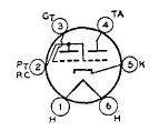
RCA called them Electron-Ray Tubes, but they're most commonly known as "magic eye" tubes now. The actual symbols vary depending on what goes on inside—there are a number of different types available—but this is a very common version, the 6E5. Here, the second grid is internally tied to the plate (Pin 2). Pin 4 is the "target".
On some magic eyes, the Target symbol is slanted.
Ballast
Ballast tubes are typically used as voltage regulators. They're called cold-cathode because there is no filament to heat the cathode.
Here the cathode is shown as Pin 8, a circle in the center of the tube. The dot near Pin 7 refers to this being gas-filled.
Picture Tubes (Kinescope)
Kinescope was RCA's early name for television picture tubes, so I've used it here because they appear in the ubiquitous RCA manuals as such.
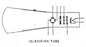
In the manuals, the schematic diagram for a picture tube looks like any other tube (round shell and all the usual elements inside). In some schematic diagrams of televisions or devices that use picture tubes (e.g. oscilloscopes), however, they use something more like this.
There are many other tubes, but those the ones you're most likely to run into.
