
![]()
I don't know if this is really going to be a project or not. As I type this, it's on its way. The backstory is this:
I was complaining to The Old Man about the frustrations of working on the old Airline battery radio. He hinted again that I should work on AA5s which are relatively easy and well-behaved, and that 1- and 2-volt tube systems were finicky and intolerant of mistakes.
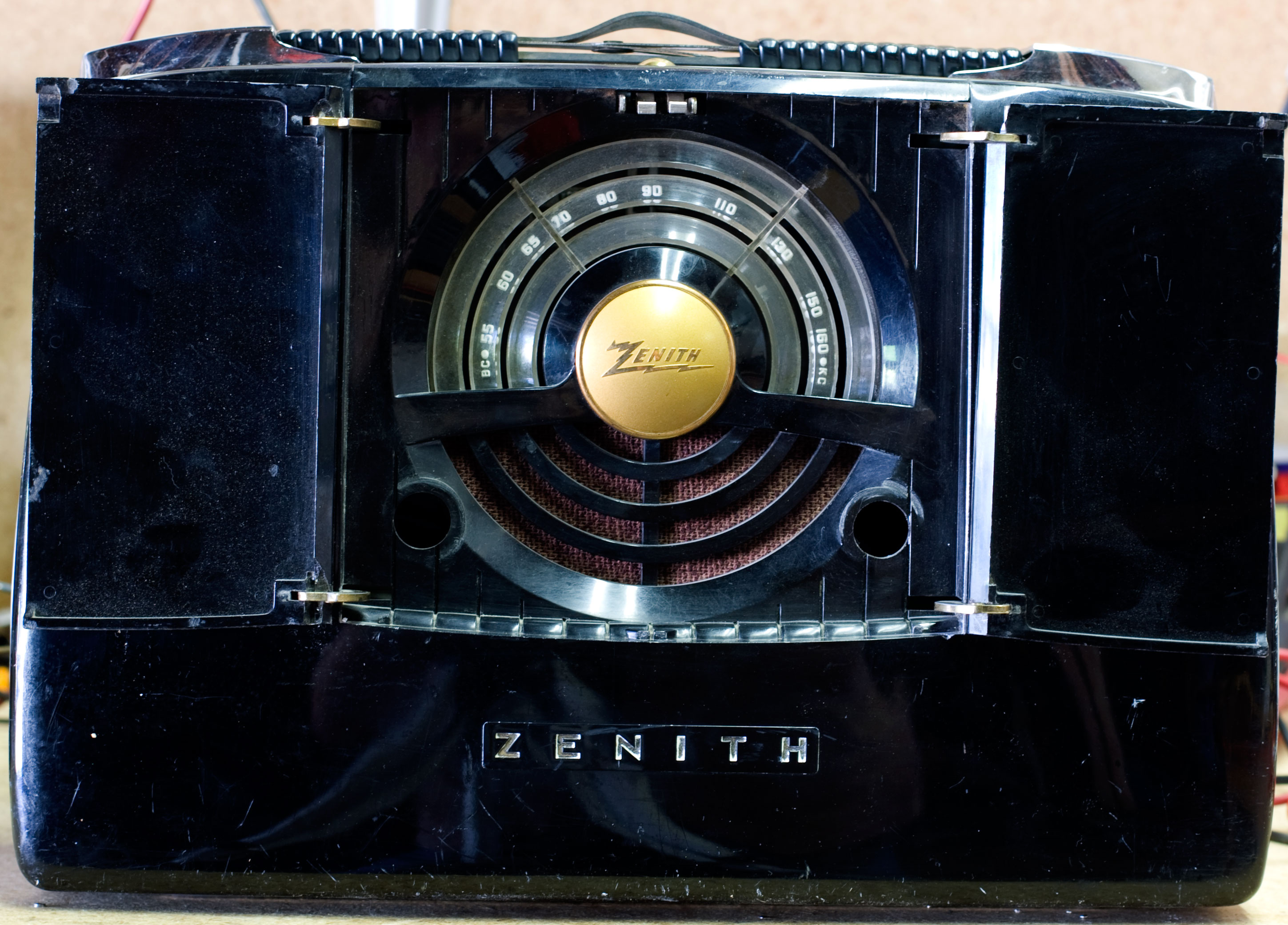
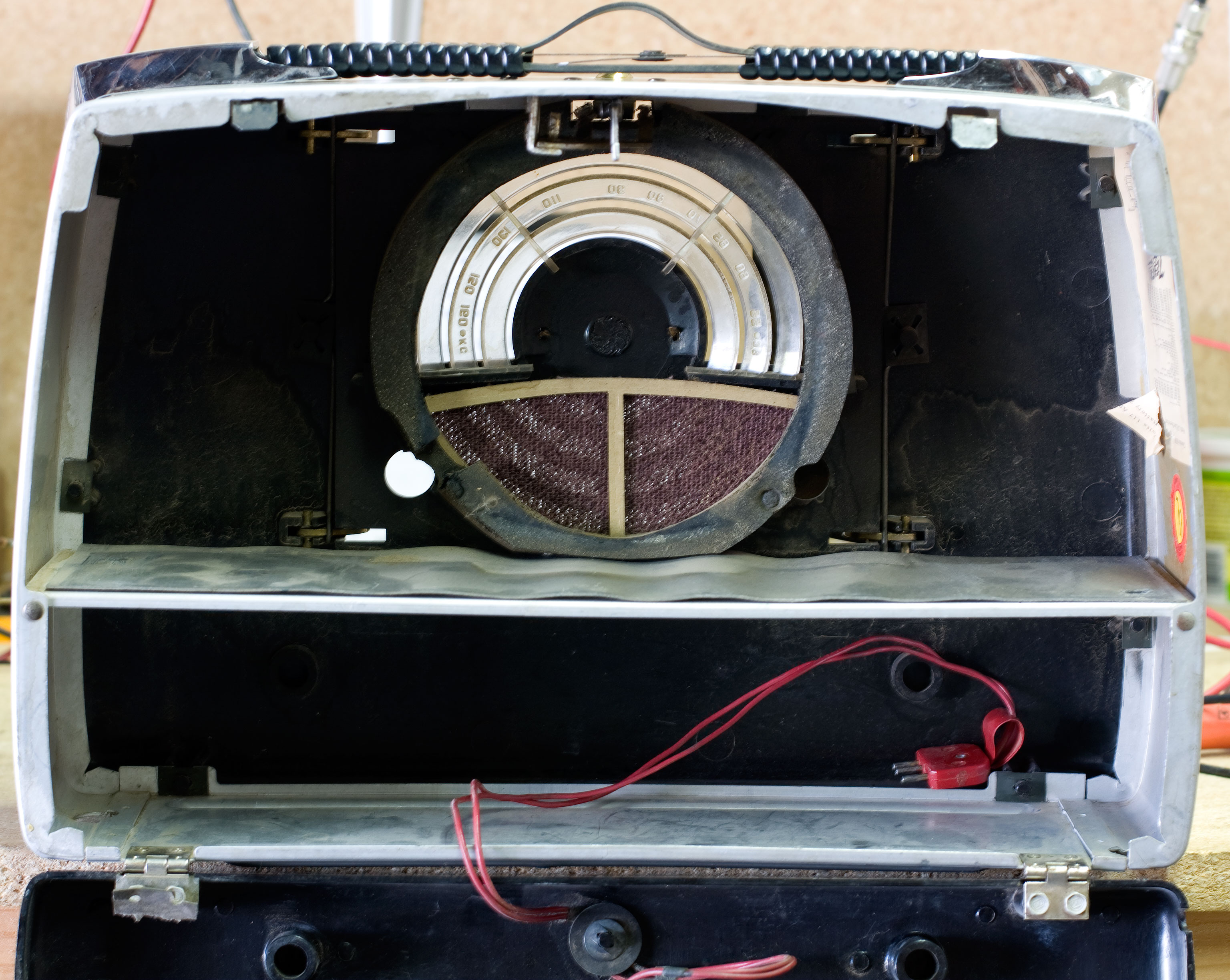
So I went on an online auction site where I buy a lot of my projects, and came across this Zenith. I don't really like what's now called mid-century styling, and the dial on this looks like the front-end of a '51 Studebaker. But I really liked the folding doors in front and (to a lesser extent) the pop up antenna panel in the back.
I looked at the photos and saw what I recognized as loctals—the unloved, evil sister of the octal tube base, except that loctals have that groove in the stem that's supposed to hold them in place and keep them from rattling out of their sockets (and have a reputation for being difficult to pull when you do want them to come out). No problem, I thought. So I put in a good bid.
 Next I decided to look up the schematic. I know better than to do this because it jinxes things. If I'm interested in a radio in an auction and I start doing the research and gathering the information I'll need for it, I never win. But I went ahead this time anyway. I looked at the tubes and — they're mostly 1-volt loctals. Two 1LN5s, a 1LA6, a 1LH4, a 3Q5GT and (maybe) a 117Z3.
I knew as soon as I saw those 1-volt tubes that I was going to win that auction.
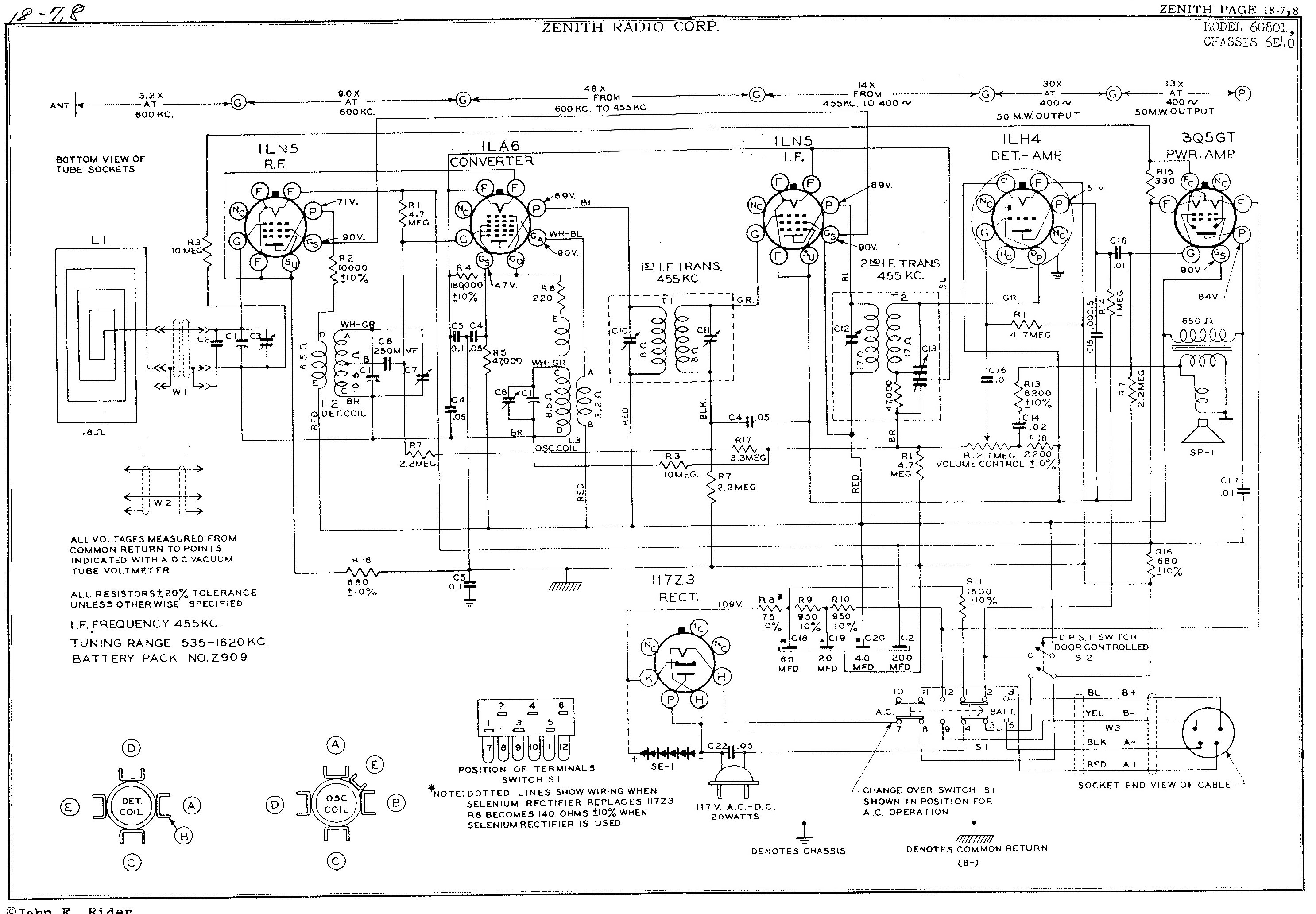
Here's the schematic if anyone wants it. I took the Rider manual from Nostalgia Air and stitched it together. As always, click on it for a larger (legible) version.
One of the interesting things about this radio is that came out around the time that selenium rectifiers became available. Power rectifiers are the first place where solid-state components replaced vacuum tubes. It made good sense—selenium rectifiers were much smaller, lighter, and didn't draw as much power as a vacuum tube. You didn't have to leach off power to run another heater. It was win-win-win all the way around.
 The bad part is that selenium is nasty stuff; and like vacuum tubes but unlike silicon diodes (which came later on), they have a definite service lifespan and then they die. But whereas a vacuum tube usually just *tinks* like a light bulb and that's it, selenium rectifiers can blow and spew out nasty smoke. So between the fact that selenium rectifiers from this era are likely to be shot, and that it's relatively easy and inexpensive to swap them out for docile silicone diodes, you just go ahead and do it.
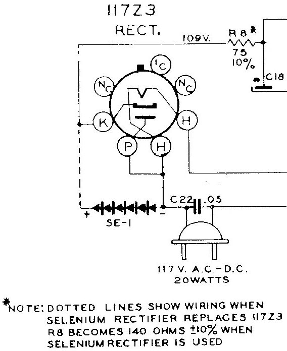
Here's a detail of the schematic (note that I erased distracting elements and moved the note, so it's not a perfect match to the original). The dotted lines mean that this radio could have either component. Which one do I have? I won't know until it arrives. But it also means that even if I get the version with the tube, I could cut it out and put a silcon recitifier in its place anyway.
There's an interesting pdf article on replacing selenium rectifiers with modern silicons. The jist of it is that he suggests using a 1N4007 which is rated at 1000V @ 1A, which means the rest of the Zenith would melt long before the rectifier does if it sees that kind of power. You also have to add resistance. The selenium rectifier has a lower internal resistance than the 117Z3 tube (see the note on the schematic—they beef up R8 if selenium is used). You have to do that again if you substitute silicon for selenium, as the silicon diode has less internal resistance than the selenium. The author's suggestion is to swap various power resistors (at least 1W) in until you get the final output voltage you want.
And Here It Is
Arrived this afternoon. FWiW to anyone who cares: the ShopGoodwill.com Tucson, Arizona store really has its act together. They ship fast and they pack stuff nicely. I can't say either of those things for all of their locations.
Back to the radio:
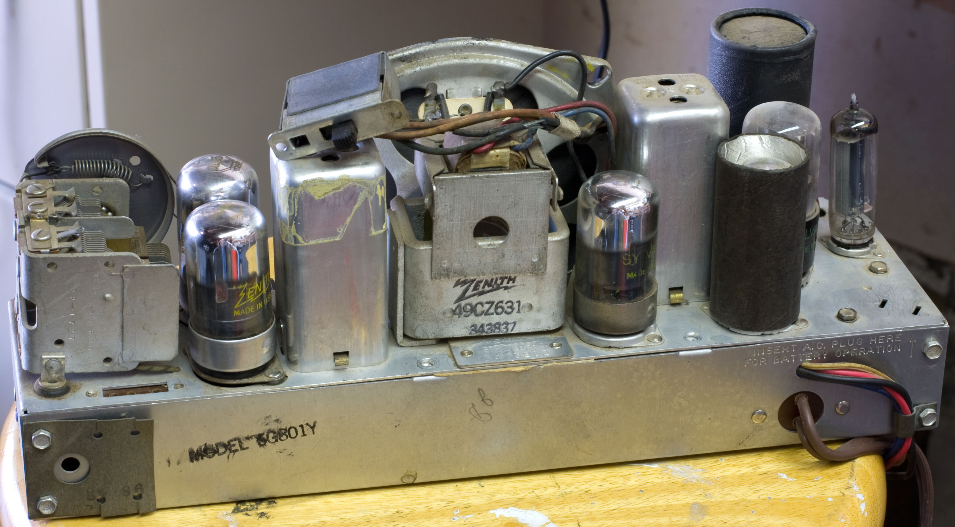
It turns out I have the one with a 117Z3 rectifier tube. I was debating about replacing it, but decided I'd do it if/when the tube goes out (since I don't have a replacement anyway) or if I'm feeling adventurous. In the meantime, I have other fish to fry with this thing.
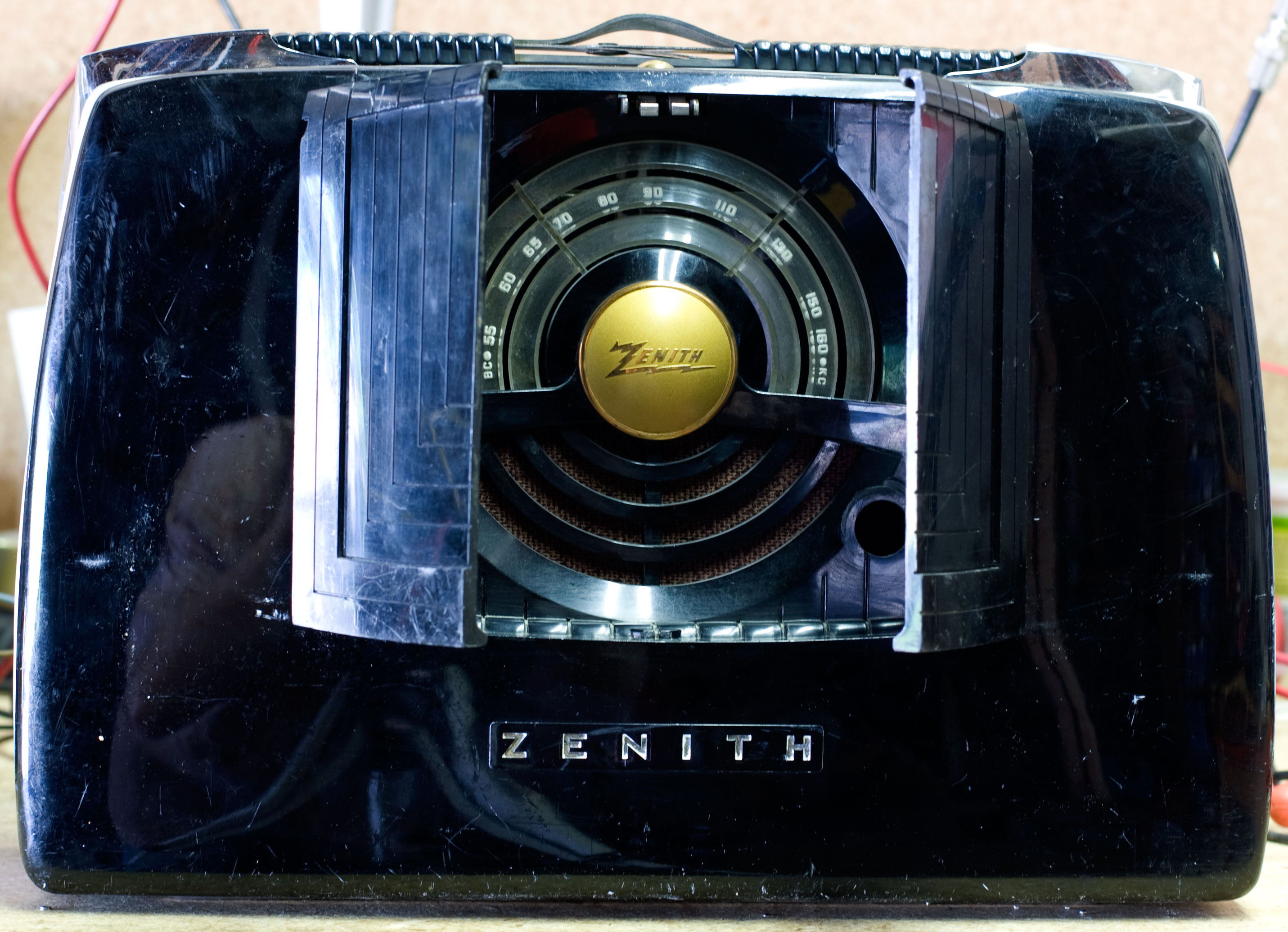
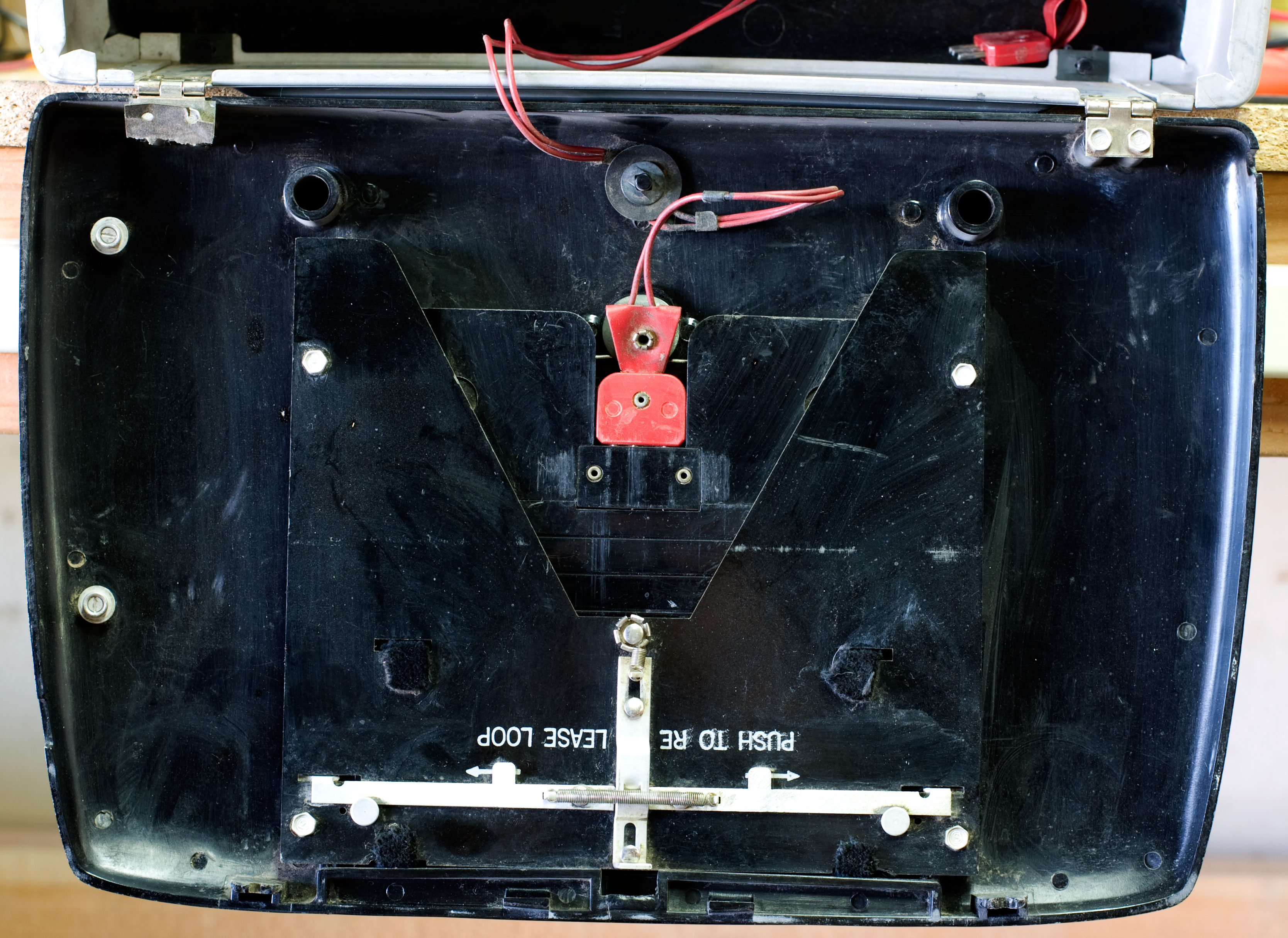
Cosmetically it's in good shape. Some scrapes and scratches, some of which may polish out, the rest are going to be character. The bad part is the front doors. The bottom hinge on both are broken where the door attaches; the problem is part of the plastic broke away. To fix it I'd have to make up something and glue it. That'll be interesting.
The other fault with the doors is the latching mechanism. The doors act as the on/off switch, so there's the action of flipping the power switch, plus the latching action to keep the doors closed or let them swing open. This appears to be a contraption, and whatever was on the door is also broken away. I'll have to see if I can locate a photo of a good one and see what's missing.
Best case scenario would be that I find someone with a junker and I can buy his doors. But that brings up one of the Undeniable Truth of Radios: the cost or difficulty of finding a replacement part varies proportionally with how important it is.
One really nice thing, though: the two knobs are the same as the ones off certain Trans-Oceanics. Luckily I don't have to replace them, but since people prize T-Os, it's generally easier to get parts.
As always, click on a photo to see a larger version of it.
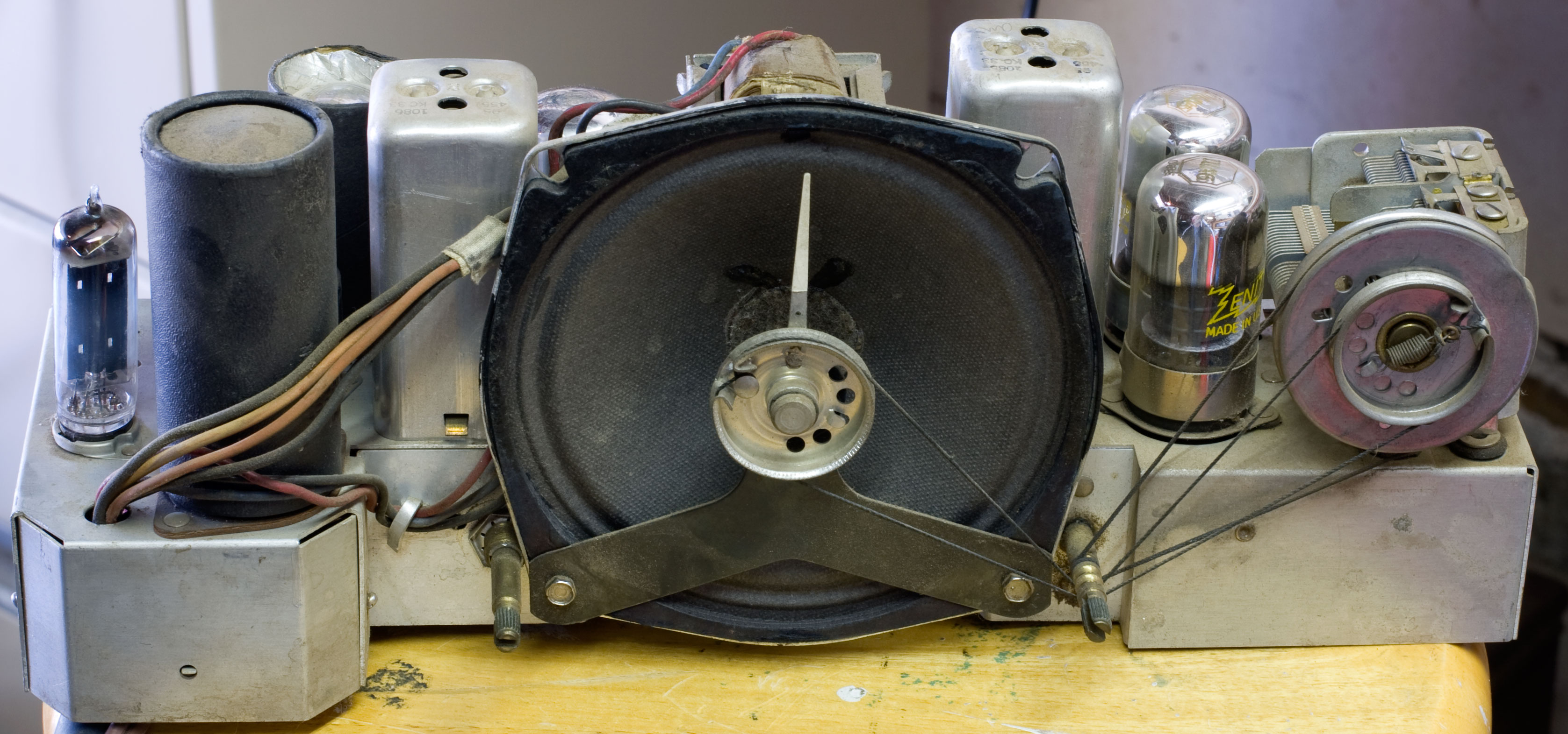
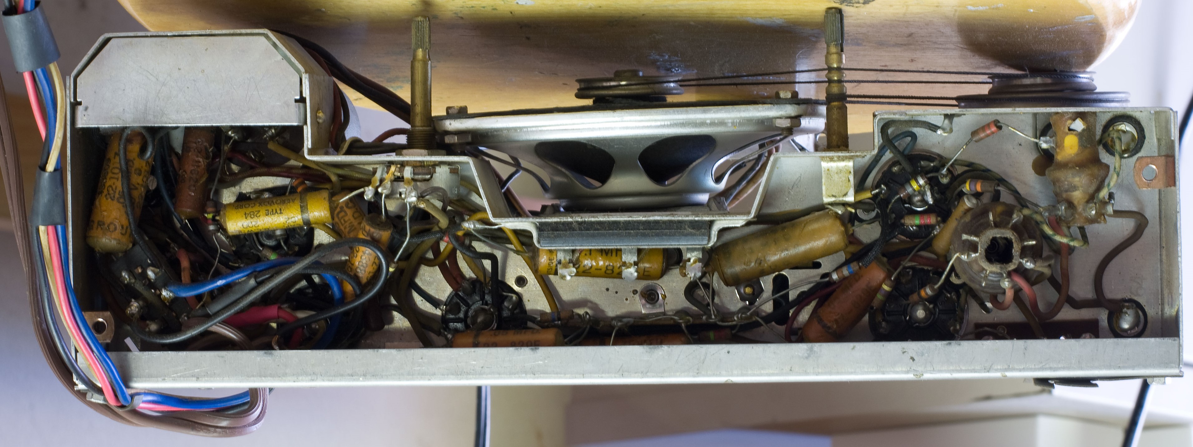
Checked the tubes—they're all good. Plugged it in and got huge A/C hum, so the filter cap is shot. If you're looking at the chassis front, that's the big black cylinder on the left side. I was thinking about cheating and just tacking in caps underneath, but there isn't a lot of room down below, so I may have to remove the cap and restuff it. Hopefully the cardboard tube will come off and I can hide the new caps in it easily (ha!).
Meantime, all the caps will have to be replaced, and maybe the high-Ω resistors if I can locate them. Also a lot of the wire insulation is hard and brittle, and I'm seeing exposed wire here and there, so a lot of the wiring is going to have to be replaced.
But at least, initially, all the parts appear to be there. The tuning cap looks good, the speaker is good, and so forth. It could be far, far worse.
Replacing the Filter Cap
It's been awhile since I wrote last. The initial recapping went fine but things halted when I got to the four-stage filter cap. It's a tall can, about the size of a roll of silver dollars (Sacagaweas, not Franklins or Eisenhowers). At the bottom where it mounts to the chassis there's a double-elipse shaped phenolic plate. Eight lugs go through this plate to connect the filters with the stuff under the chassis.
Long story short, I drew up a diagram of what connected to which lug, and removed everything. I drilled out the two rivets that held the phenolic plate to the chassis, an out came the filter cap. There's a black paper cover that slides over it, so I figured I could use this to hide the new caps. There's no way I can cut open the original, metal can and restuff it. Not at my current level of expertise (i.e. tyro).
Figuring out how to make the new filter stack took a lot more thought than I would have guessed. Four lugs go through the phenoic plate making an outer ring—these turned out to be Common and they're all shorted together. But the phenoic plate has a big square hole in the center where the four inner lugs pass through. So if I want to make up a new cap stack, I had to figure out how I wanted to make these four positive connections.
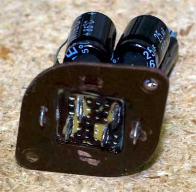 Thought about cutting heavy cardboard the shape of the square, gluing it in, and drilling four holes. Fine but I thought the card would probably burn (or at least singe) when I started soldering. Same with plastic. I finally realized I could do it with prototyping breadboard, which was made for this sort of thing. I cut a square of breadboard out the size of the hole (more or less) and glued it in.
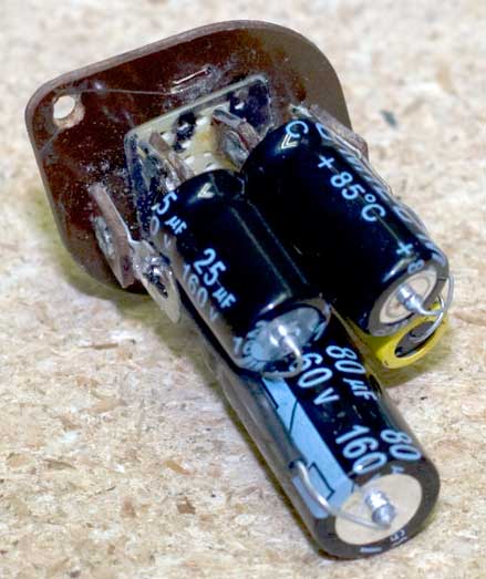
I had some old tie-point lugs from another project, and they looked like they'd fit. I drilled out some holes to make slots in the board, pushed the lugs through so one half was above the board and the other half was below. I soldered my capacitors in place. And there you go—a new filter stack. It isn't pretty, but I think it will do the job.
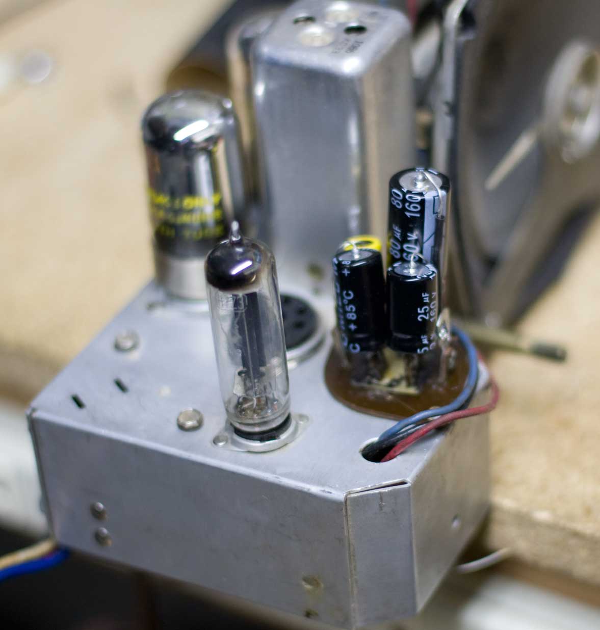 The next step is to mount it back onto the chassis (I don't a rivet gun so I'll probably just use machine screws and nuts), and then start connecting up the below-chassis components again. This will be tricky—when I made up the original diagram I didn't know which lug was which value on the filter cap stack. So I'm going to have to figure out what component I want to connect and which lug I want to connect it to. The upside is that I can easily see which cap is which. When I'm done, I'll drop the cardboard cover back on it and it'll look "original."
September 2013: A Side Note
I just got another one. This one is the brown case version, which I don't think looks as handsome but it works. The doors latch and unlatch properly. Unfortunately it also has some sort of problem. The eBay seller had said it didn't play. Turned it on figuring I'd hear AC hum, but no—it's quiet. The 3Q5 power out tube tested terribly weak, so I swapped out for the known-good one and tried again. Static but nothing. I looked but didn't see anything obviously wrong. I tested the tubes and though some of them test weak, they test weak on my black unit too. They're 1 volt tubes so I'm not confident yet whether they're at fault or not. Anyway, I do not want to pull the chassis on this one yet. I'm going to use it to help me figure out how to get the chassis back in the black-case when the time comes.
Meanwhile I'll order some tubes, because of course I don't have any of these already. Luckily they're all inexpensive.(8 Sept 2013)
October 2013: Trust Nothing
I got a nice email from another 6G801 owner, and I vented my frustration in a reply. Where I am now is this: I had to disconnect about 15 things in order to remove the filter cap, and reconnecting it is turning out to be far more difficult than I'd thought. Part of the problem is that when I was drawing up diagrams and notes during disassembly, I didn't know which lug went to which stage of the cap. So the black wire from terminal 1 went to the lug in the upper left, but which filter cap was that? Dunno.
That shouldn't be a problem except that it appears that my chassis layout deviates from the schematic I have. A wire that I cut that absolutely, positively goes to one of the positive terminals on the filter cap can be traced to a particular place: but on the schematic, that wire goes somewhere else.
I thought it was just me, but the Old Man went over it and eventually concluded the same thing. So it looks like now I'll have to pull the chassis from the 2nd radio in order to use it as a wiring model. I was hoping to avoid that since I wanted to use it as a model in putting it all back together to make the trick doors work. So I'll have to document the 2nd radio's disassembly very carefully.
And I'll bet you before this is done, I'll have a 3rd one of these to use a model to put the previous two back together again.
Current status: this radio is no longer in my collection. This page will be removed in late 2024.