
You meet a space-alien who has come to earth. He gives you an odd-looking device and says that it will create World Peace. What do you do?
- Give it to the President of the United States?
- Give it to the Secretary General of the United Nations?
- Take it apart and see what's inside?
Teardown Tuesday comes from the wonderful EEVblog and I decided to use the idea myself. I couldn't come up with a better clever title that rhymed with a weekday (Wreck-It Wednesday came close, though). Since I had a couple of things on the bench that had to be opened up anyway, I thought I'd make a page of it.
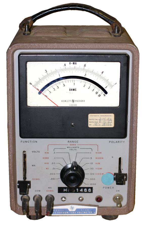
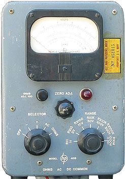 Hewlett-Packard 410B VTVM
FYI: I no longer have this in my collection.
I started like this. I didn't read the manual. Actually I did read the manual but a) I'm easily overwhelmed, b) it was a while ago, c) I'm an idiot, and d) I didn't pay attention to the caution. Not the one that was in the middle of a pertinent part of the manual, and not the one that's a full page at the beginning of the manual. I didn't pay attention because I thought it was another one of those Don't play with matches warnings that lawyers love to fill manuals with.
This is what the warning is: the "common" probe is connected to the 410B's chassis-ground, so chassis-ground becomes ground potential of whatever you're measuring. Okay, fine. But the 410B also has a 3-prong AC plug, and chassis-ground is connected to that third prong. So you have to be careful what you connect the common lead to because you could create an internal short and blow up the meter.
Doing this is pretty dramatic—you can't miss it. A nice bizzz-ZAP. The first time I did it, I popped the circuit breaker on the main panel. The second time I did it (another location) it only tripped the GCFI breaker on the outlet. But the second time I also killed the meter.
Now I could have just packed it in a box with a $100 bill and sent it off for repair, but I thought I'd take a look first. As Bill Cosby said at the beginning of Fat Albert episodes, if you're not careful you might learn something before it's done.
The only manual I have is the free one that everyone on the internet seems to have, which is a later edition. HP made this meter for almost a quarter-century; and even though the basics are always the same, there are refinements and changes. Someone on eBay has the manual that's appropriate for my serial number, but he wants $36 for it. No way.
So after the obvious (replacing the 1A fuse), the manual suggests checking the tubes first. There's a 6X4 rectrum-fryer (gets nice and hot), two 6189s (more commonly known as 12AU7s), one voltage regulator OB2 and an Amperite 6-4 current regulator. There's also a little 2-01C diode in the AC probe, but I figured its loss wouldn't kill the whole meter. The regular tubes all passed fine on my Hickok 600. I checked the ballast tube using the method described in the HP manual and it seemed okay. The Amperite seemed okay. I didn't pull the 2-01C but was surprised to find that it appears to work (it certainly does its job as a hand-warmer); that amazed me because of all the tubes, it was the pricey one. If you're going to blow a tube, it will alway be the most expensive ones that go first.
That kind of forced me to focus and try to do things systematically. I checked continuity on the probes—okay. That took a little doing since the the DC probe turns out to have a 22MΩ resistor inside. They passed. I visually inspected as much as I could see inside to see if there any broken components, burns, or other signs of damage. No, not really.
Turned it on and tried the functions again. Ohms: dead. DC—worked! I checked a 9V battery on both polarities. AC—I had to be extra careful because this was how I blew the meter to begin with. I found a wall wart that outputs AC and plugged it into my isolation transformer, and got a reading.
But the Ohms were Jacob Marley at the beginning of A Christmas Carol. Got continuity through the cable. According to the schematic (admittedly a later model than mine), there's no resistor in the probe. Looked at the manual and they suggest that the resistors in the Ohms range switch be checked, as I may have blown one or more of them.
Here are the photos. Click on them to get larger versions.
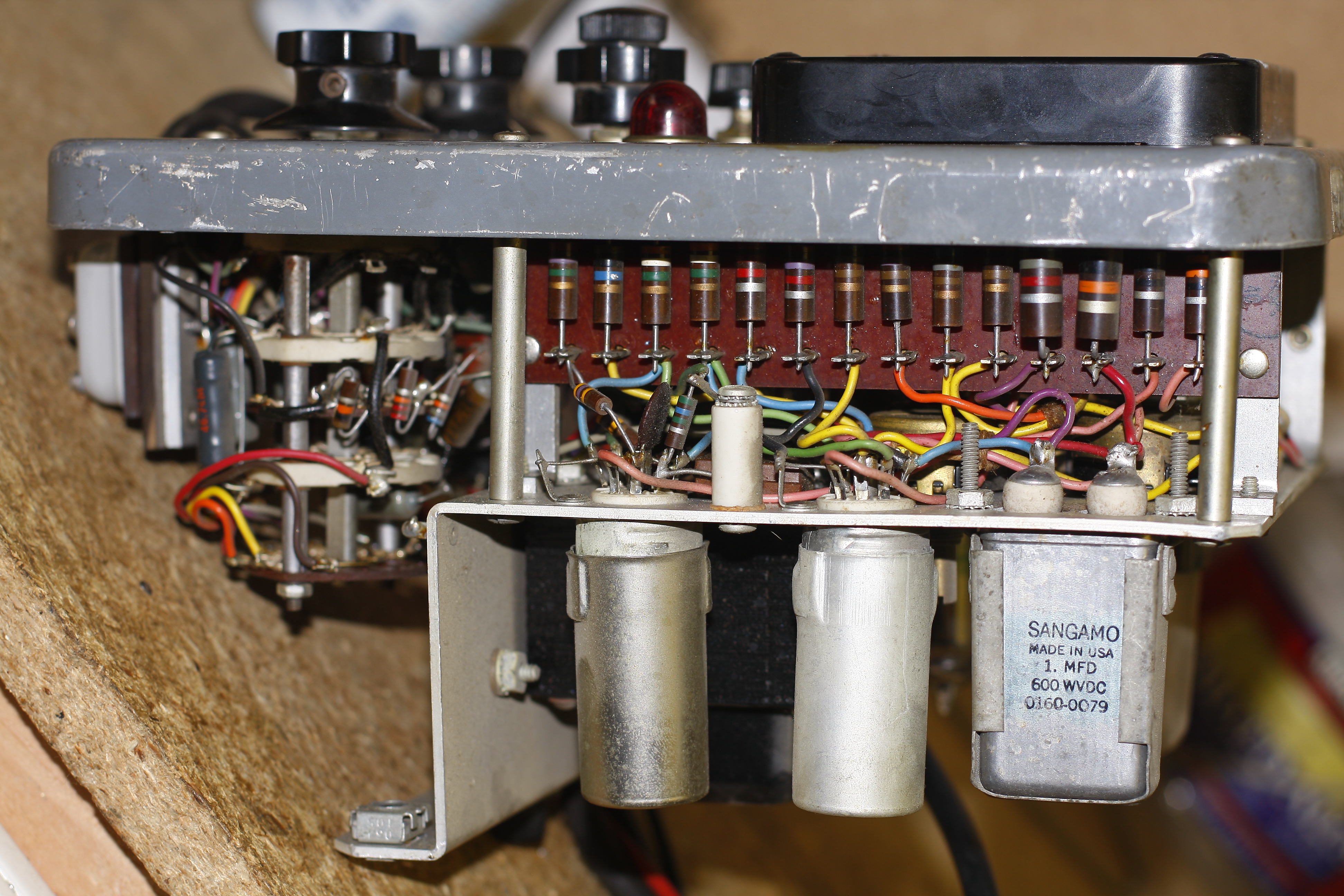
This is the meter's right-hand side. The tubes (upside down) are (left to right): Amerperite 6-4, 0B2 ballast, and the 6X4 rectifier.
This is the view from the meter's top. Those are the top calibration pots.
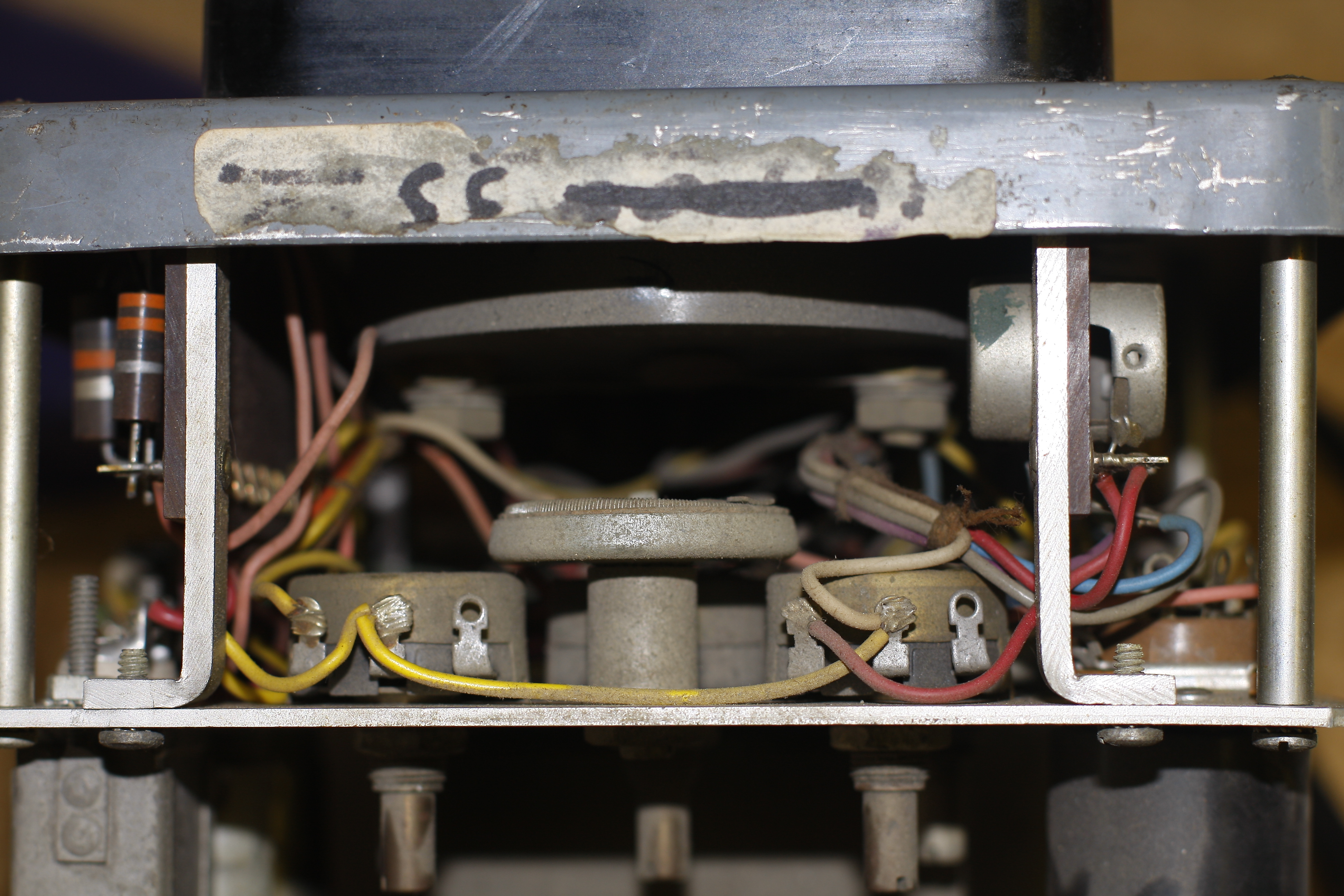
This is the meter's left side. On the left is the range switch; the upper right is bank of resistors; below are the two 12AU7 tubes (mine are actually 6189s, but they're the same thing). The can is a Sangamo 1µF filter cap. Later revisions of this 410B replaced that with a beefier 4µF can.
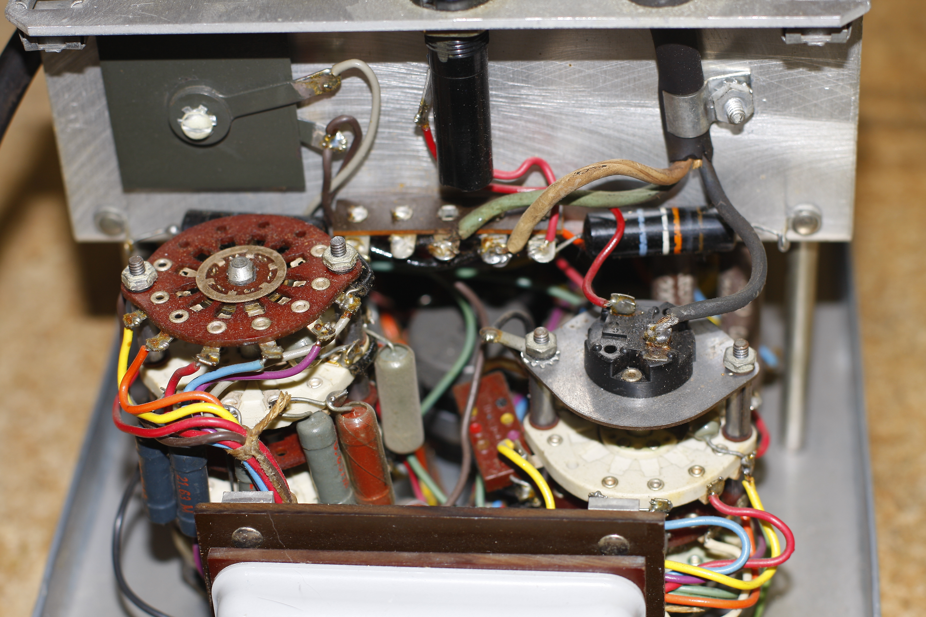
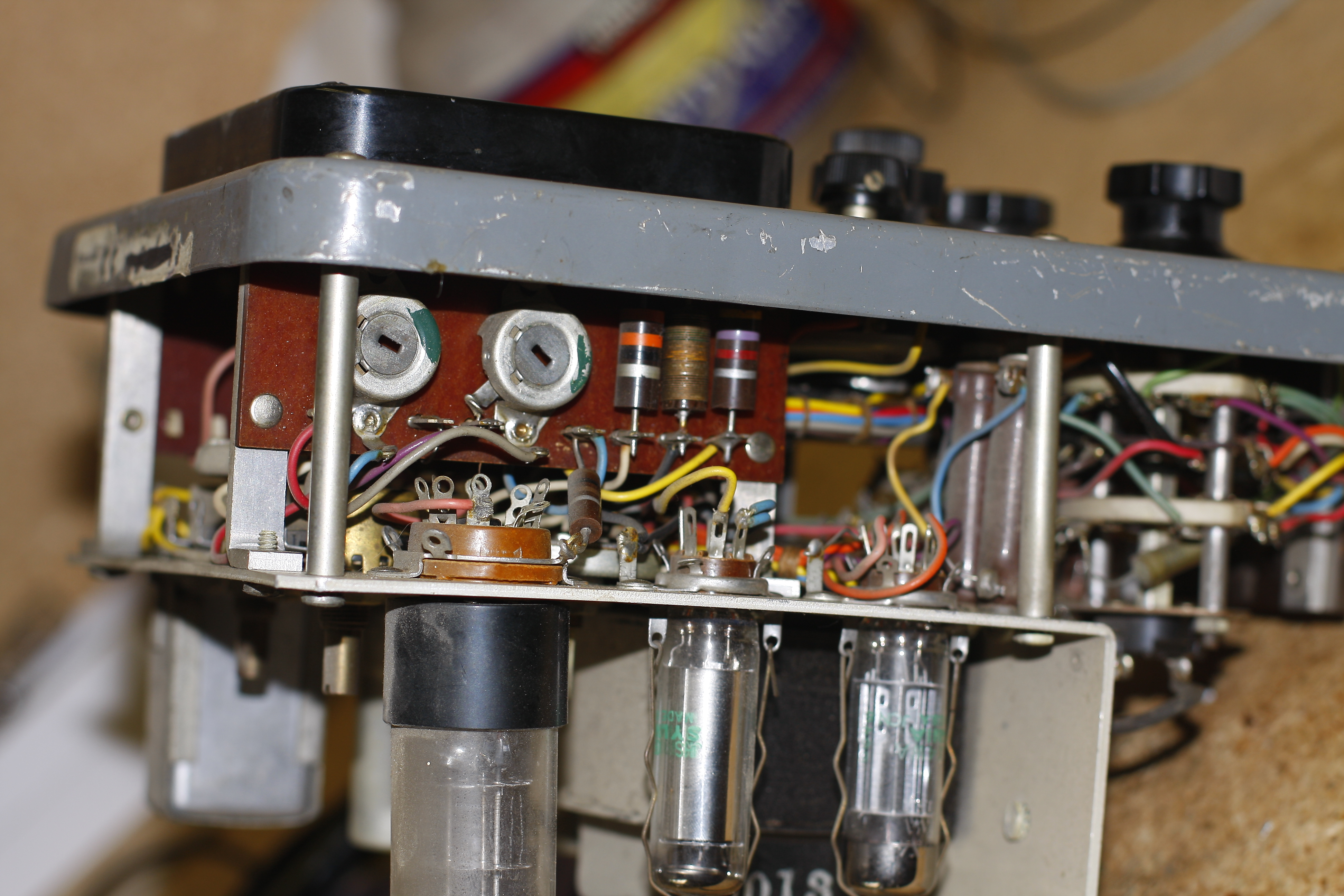
This is the meter's bottom. On the left is the range switch; the right is the mode switch. The white tub on the bottom (partially cut off on this photo) covers the probe wire terminals.
I went through it and checked the values of every resistor I could reach, and everything seemed okay. The ones on the range switch are tough to get to; I ended up having to undo the switch from the panel so I could get to more resistors—including the ones the the manual said might be fried. They all measured as rated. I put the switch back in and fired it off again to make sure I didn't inadventantly break something else. And the ohms came to life! Well, for a few minutes anyway. I switched to DC and AC to see if they still worked, and back to ohms and it's dead again.
Everything was all over the road, so I unplugged it, gave it some time to cool down and discharge filters, and then blasted the switches with cleaner. If I were to do this correctly (and if I have to really pull it apart later), I'll open up the pots and clean them properly. But as it is—it seems to work. Getting the ohms zeroed on both ends takes some doing, but ultimately the ohms seemed to work, the DC voltage works. AC responds but I didn't like the test reading I got. Next step is to try to do the calibration routine.
Later.
 Hewlett-Packard 412A VTVM
This one came with its older brother, the 410B above. It's never worked right. I had the back off once and checked the tubes, but the tubes were fine (they always are) so no easy fix here.
FYI: I no longer have this in my collection.
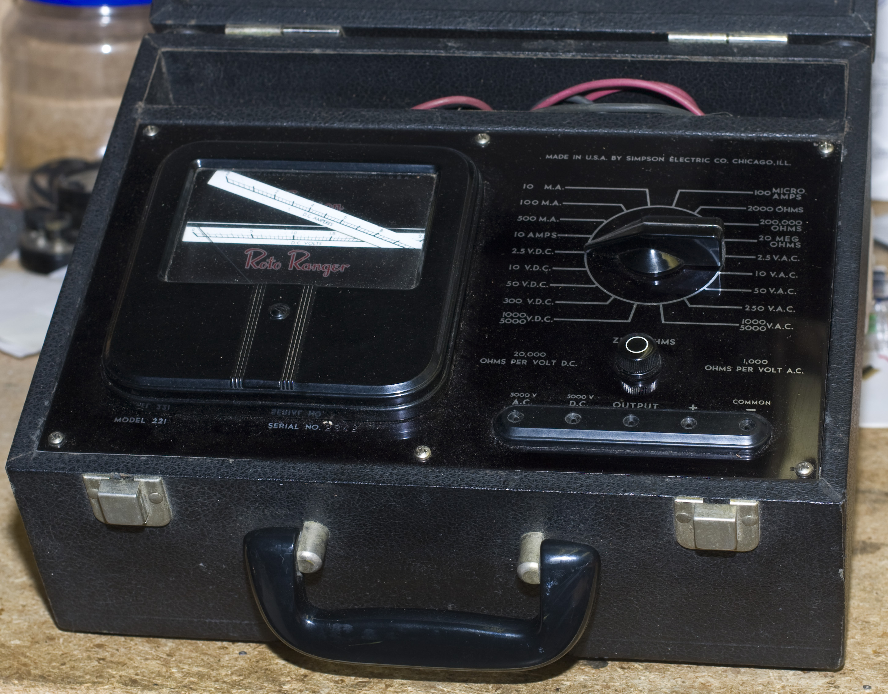 Simpson 211 Roto-Ranger VOM
FYI: I no longer have this in my collection.
The most attractive meter I owned. This one is built into a leatherette-covered wood carrying case so it resembles a tube-tester or small luggage. The meter is essentially the workhorse Simpson 260 but with a special gimmick: the meter face is masked off so you can only see a slim horizontal band. Each meter range (as selected by the knob on the right) has its own dedicated meter scale; each scale is drawn separately onto a slim horizontal card, and the cards are glued onto a cylinder, and the cylinder is mechanically connected to the selector switch. So as you turn the knob to pick a function and range the cylinder rotates and shows you the appropriate meter scale. Thus when you read the meter, you only see the scale you need; you don't have to look all over to figure out which scale you're supposed to use.
When I received the meter, one of the scale faces had come unglued and was floating around. If you click on the image (right) you'll see a larger version and it's more apparent. So were also something rolling around loose in the cabinet, so I had to open it up to deal with both those things.
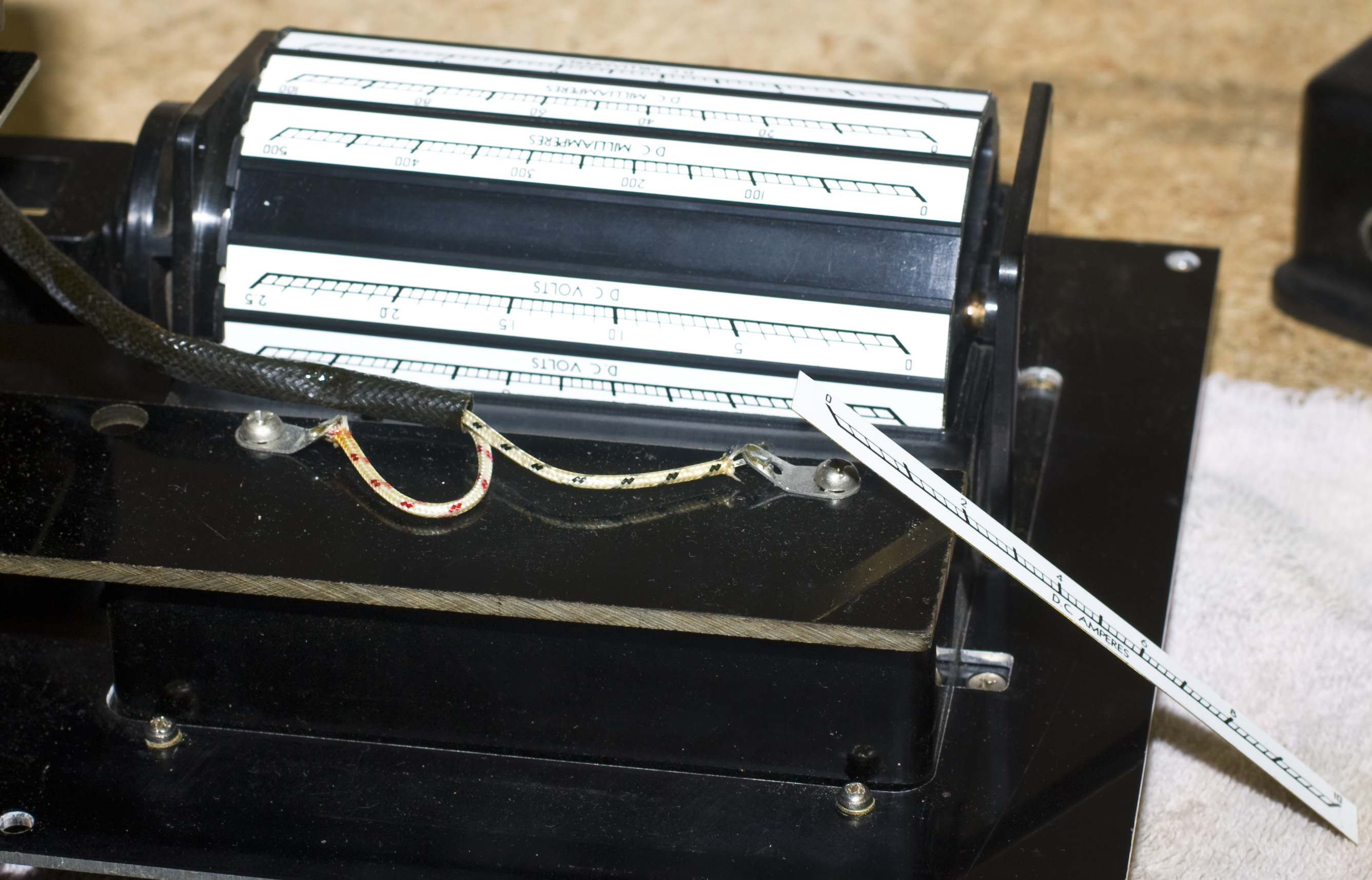
Click on each photo for a larger version. From top to bottom, left to right:
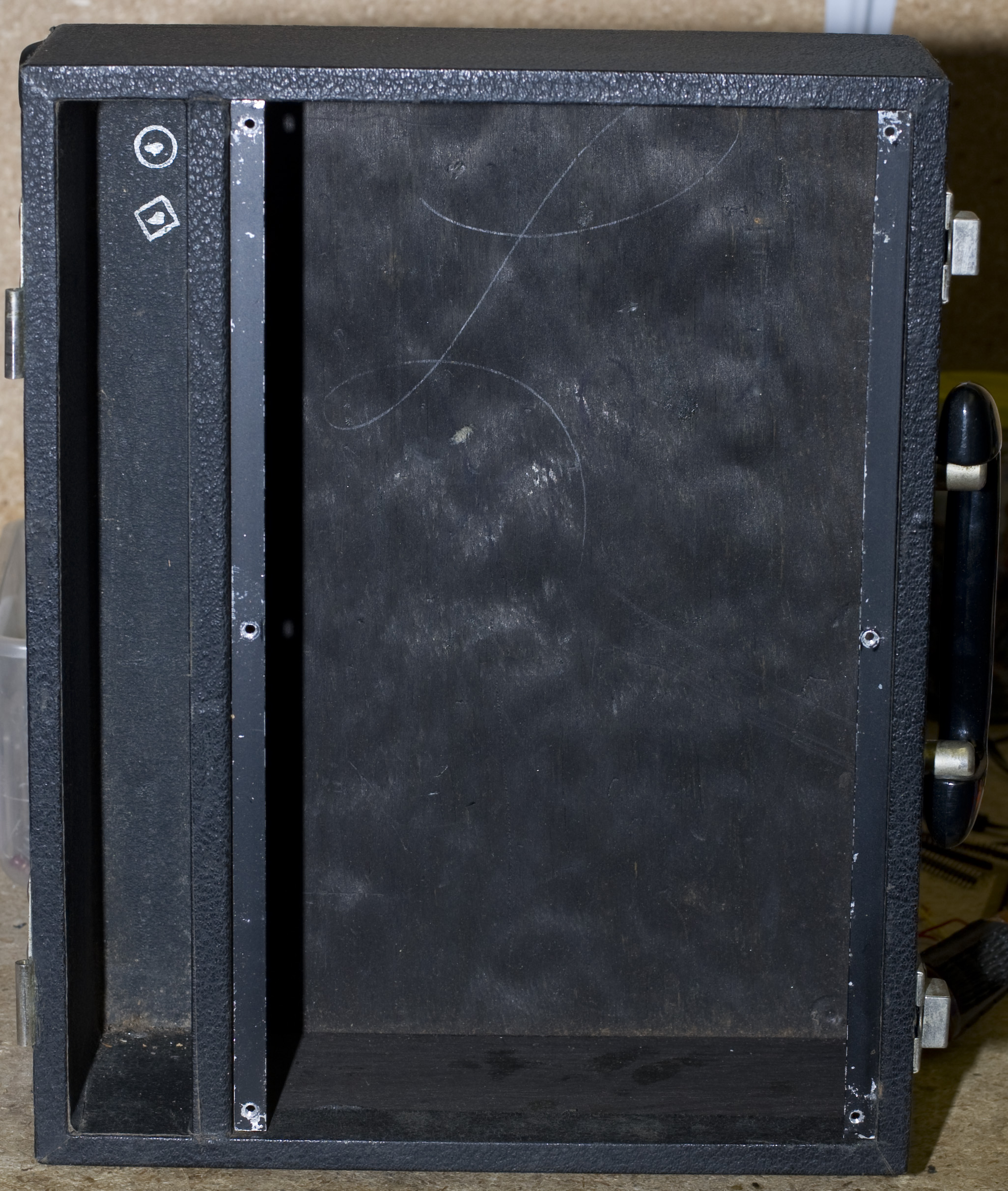
The case with the works removed. All you have to do is take six screws out of the front panel and it lifts right out. The front cover has sliding pin hinges so it comes off easily too.
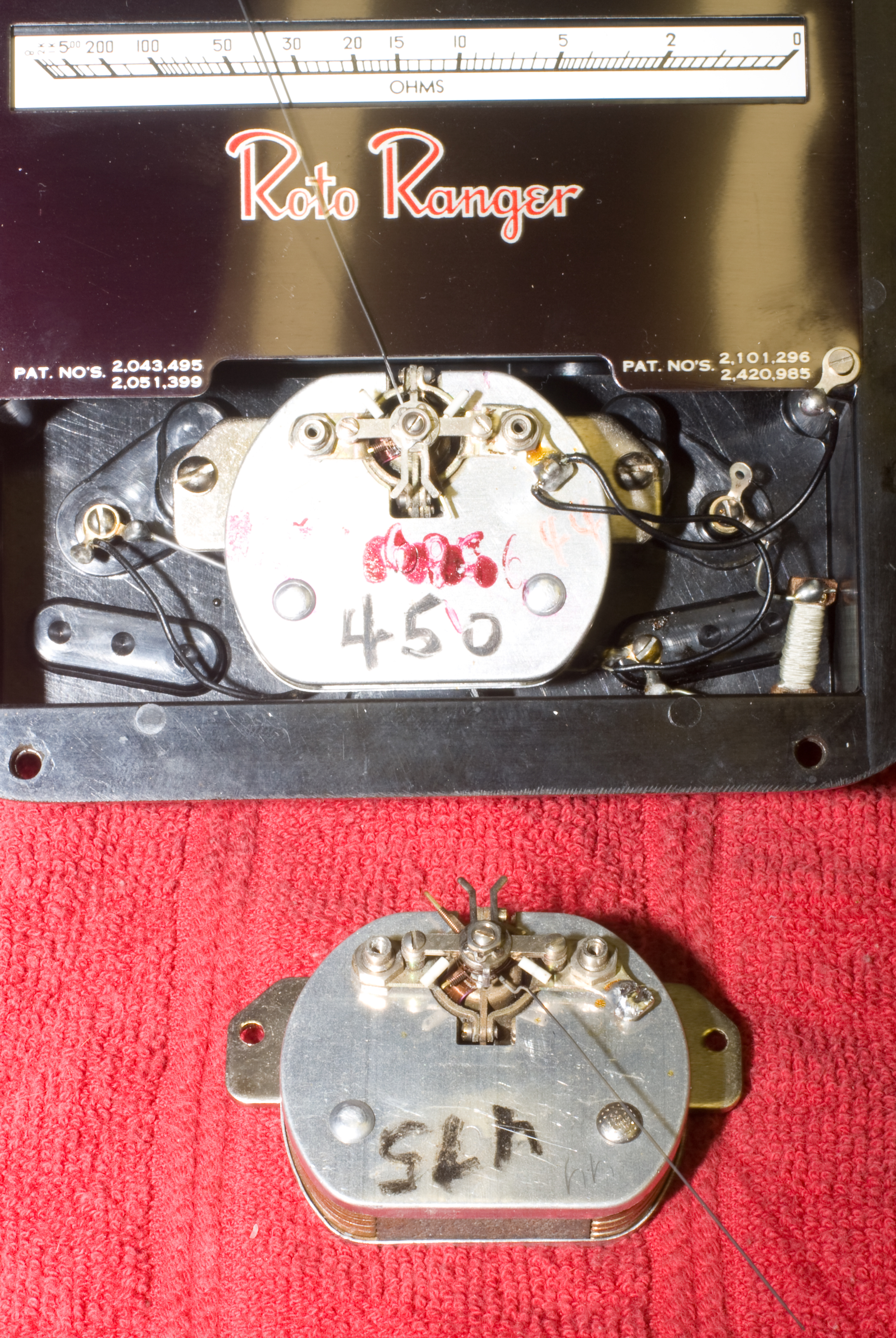
Three photo of the back side of the works from different angels. The upper two show the side with the selector knob up and the various shunt resistors and capacitor down.
Lower left; detail of the selector switch (knob down). On the left you can see the mechanical rotator that connect to the meter drum, so that as you rotate the range switch, it turns the drum accordingly.
Lower middle and right: two angles of the meter drum, after I removed the cover. Right-most shows the meter face card that came off the drum, and the place where it is supposed to go. I glued it back on.
Reassembly was easy and just a reverse of disassembly. I ended up putting fresh batteries in it (I didn't photograph that) and put it back together, and then found out the meter movement is dead. So back apart it goes!
That's the meter housing removed from the panel. The front cover (with glass bezel) was removed and set aside. Now you can see the meter mask in front of the drum, and the meter movement itself.
The meter movement turned out to be Jacob Marley at the beginning of A Christmas Carol. I even had the Old Man check it and he agreed. He also couldn't find what was wrong with it; it was something inside the moving-coil portion and that is like working on a watch.
The specifications for this meter are identical to the Simpson 260, and the era is the same—I was willing to bet money they used the same movement. I have a 260 but it works and I don't like to harvest organs from working machines, so I started looking for parts donors.
A couple of dead Simpson 260 meters showed up on an auction site and I picked them up for $20 (I'll include them on a future Teardown Tuesday entry), hoping that between them at least one would have a working movement. The cleaner 260 (a Series 3) looked good but the needle was gone. Looked it had been snipped off. Who the hell snips off a meter needle? There was no way that I could replace that. Luckily the other 260, which was older and in a lot rougher shape, had the needle and the movement responded to electricity. So I took it out and checked it against my 221 movement.
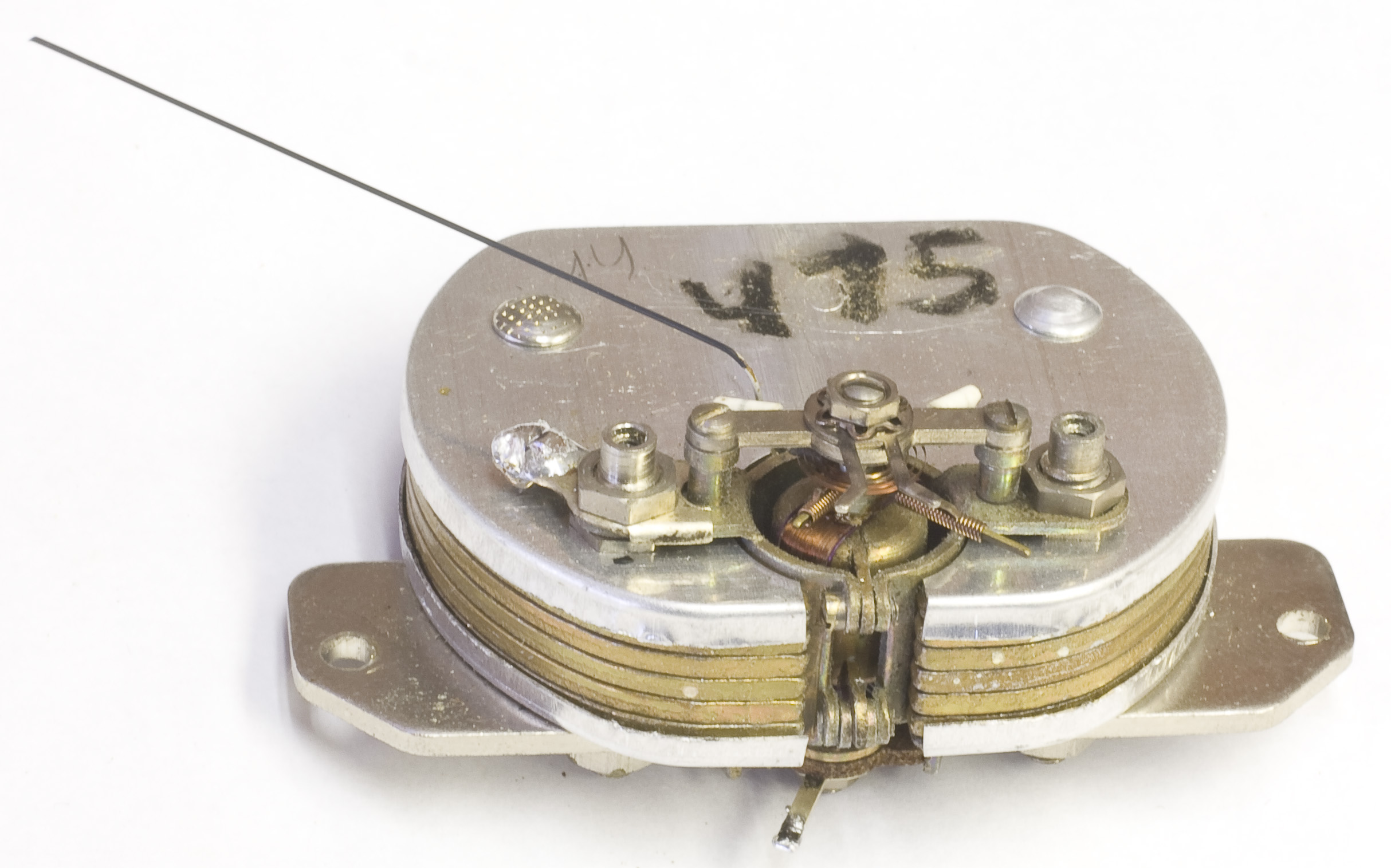
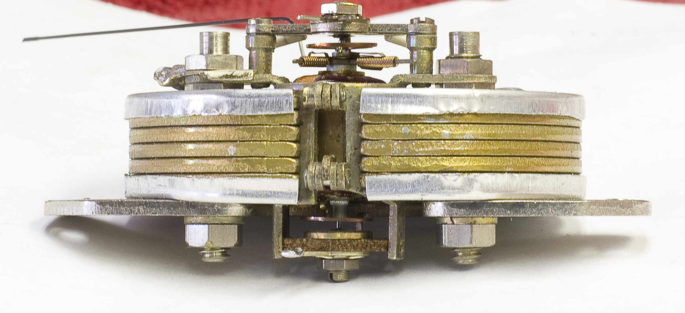
Some photos. Left-most: the range-movement (in-situ) on top and the 260 donor movement below. Take a good look—see what the problem is? The movements appear to be identical except the moving-coil portion is reversed. On the 221 the needle sweeps up across the narrow part of the plates; the 260's needle sweeps across the broad part. In order to make this work, I'll have to take the moving coil assembly off and rotate it 180°.
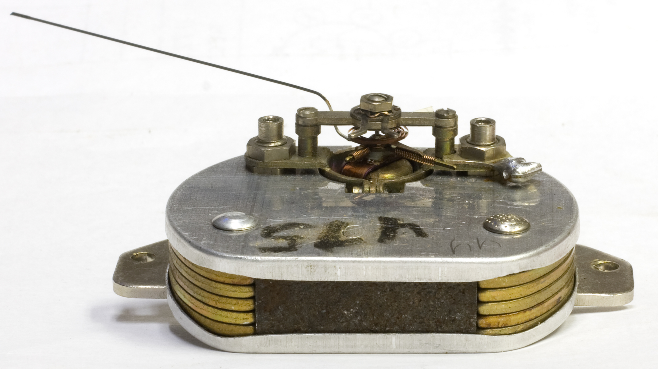
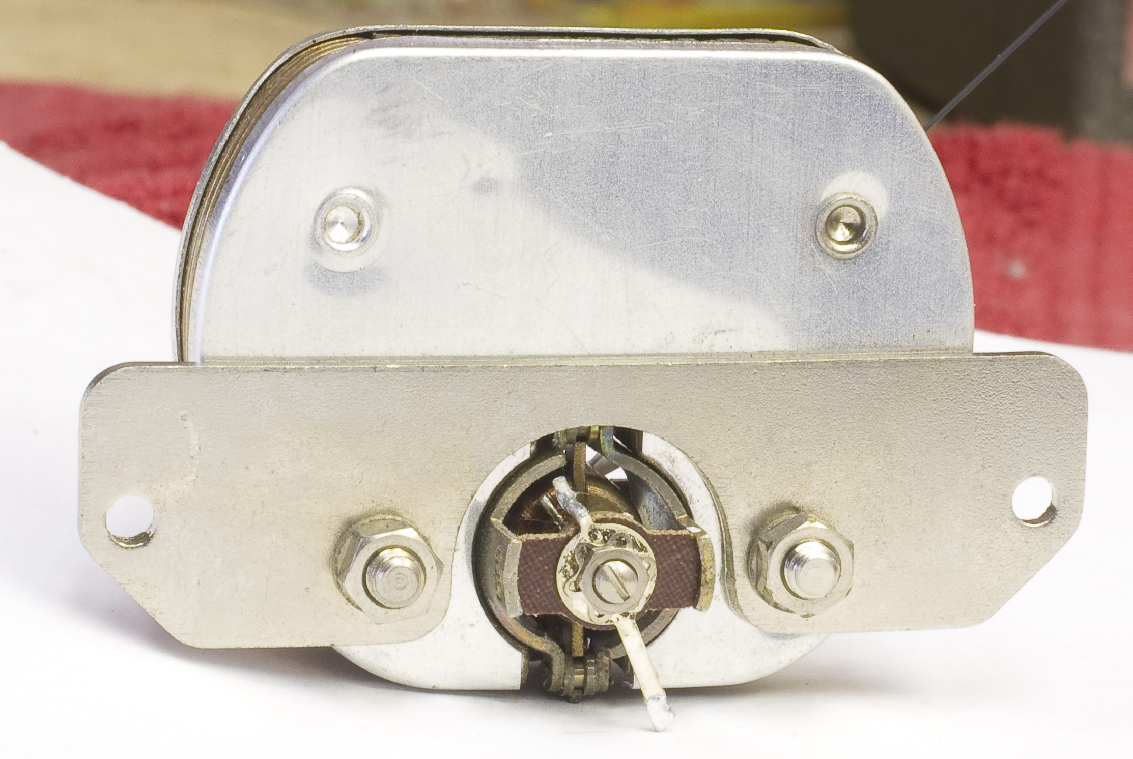
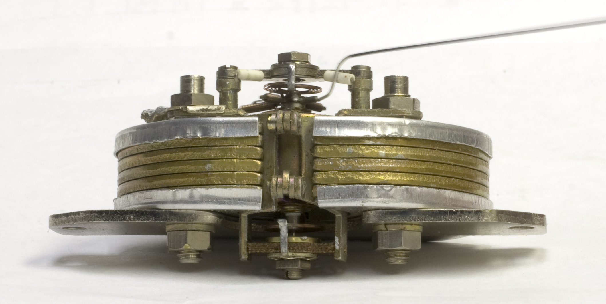 More photos. Here they are after the reversal. It's actually easy to do—you back off the two small nuts on the top (needle side) and then the whole assembly can be pulled out in one piece. Rotate it 180° and then push it back in. The only real problem is that there's a stem on the rear where a wire was soldered on; it had to be bent in order to make it through the hole when I pushed the assembly back in. Put the nuts back in, straighted out the wire, and I was (almost) good to do. That stem rotates and it affects the tension on the meter springs and where the needle rests. I couldn't find a natural place for it to be, so I guessed.
 No photos of reassembly, since it's all just reversal of disassembly. Tacked the wires back on, set the movement in and bolted it down. Cover on. Meter housing back into the front face plate, bolt down. Make sure the range selector was locked in properly. Reattached the meter wires. Soldered a broken lead going from a capacitor to the front panel jack.
Fresh batteries in. Unit back into the cabinet. Knobs on. Complete!
The results? Mixed. The ohmmeter works but the meter is a bit squirrelly; not sure if the movement needs adjustment or it's just oxydation and crud on the test leads. Probably both. No function on DC volts. Didn't try AC or current. I'll come back to that later. At the moment it's better than when it arrived, and I'll take that.
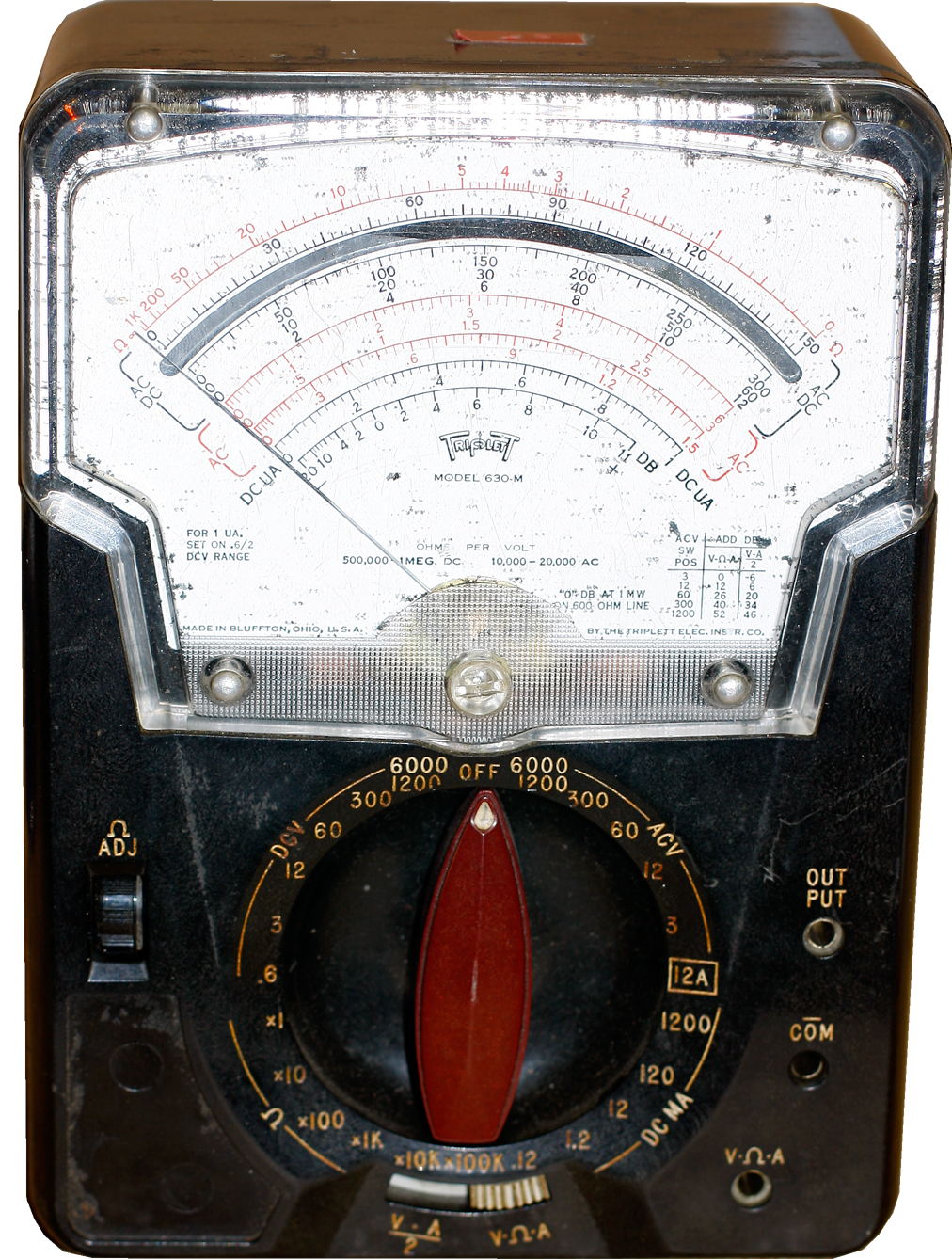 Triplett 630-M VOM
FYI: I no longer have this in my collection.
This one arrived in rough condition (which is why I could afford it). Besides missing the decal in the lower left corner (it says that there's a 1000V limit), a missing handle, a crack in the case, two missing case screws, various scratches and such, there was a detached mirror floating behind the meter face, and a lot of black dust and debris inside the face, under the glass. That's the worst, as far as I'm concerned, because it would be the most likely to clog or break the meter movement itself.
Doesn't work, it needs to be fixed anyway—nothing much to lose so might as well open it up.
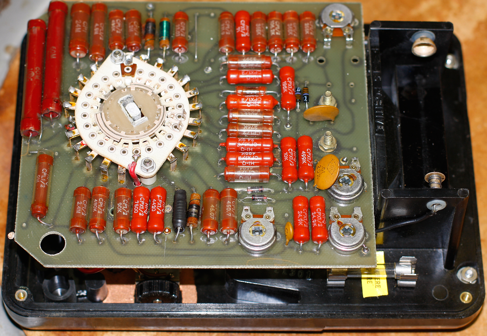
Here it is with the case off. The redhots are the precision resistors. This is the big difference between a 630-M and every other 630 variant—the other 630s have them hand-wired in a carousel around the switch. Phil's Old Radios has a nice photo to illustrate it.
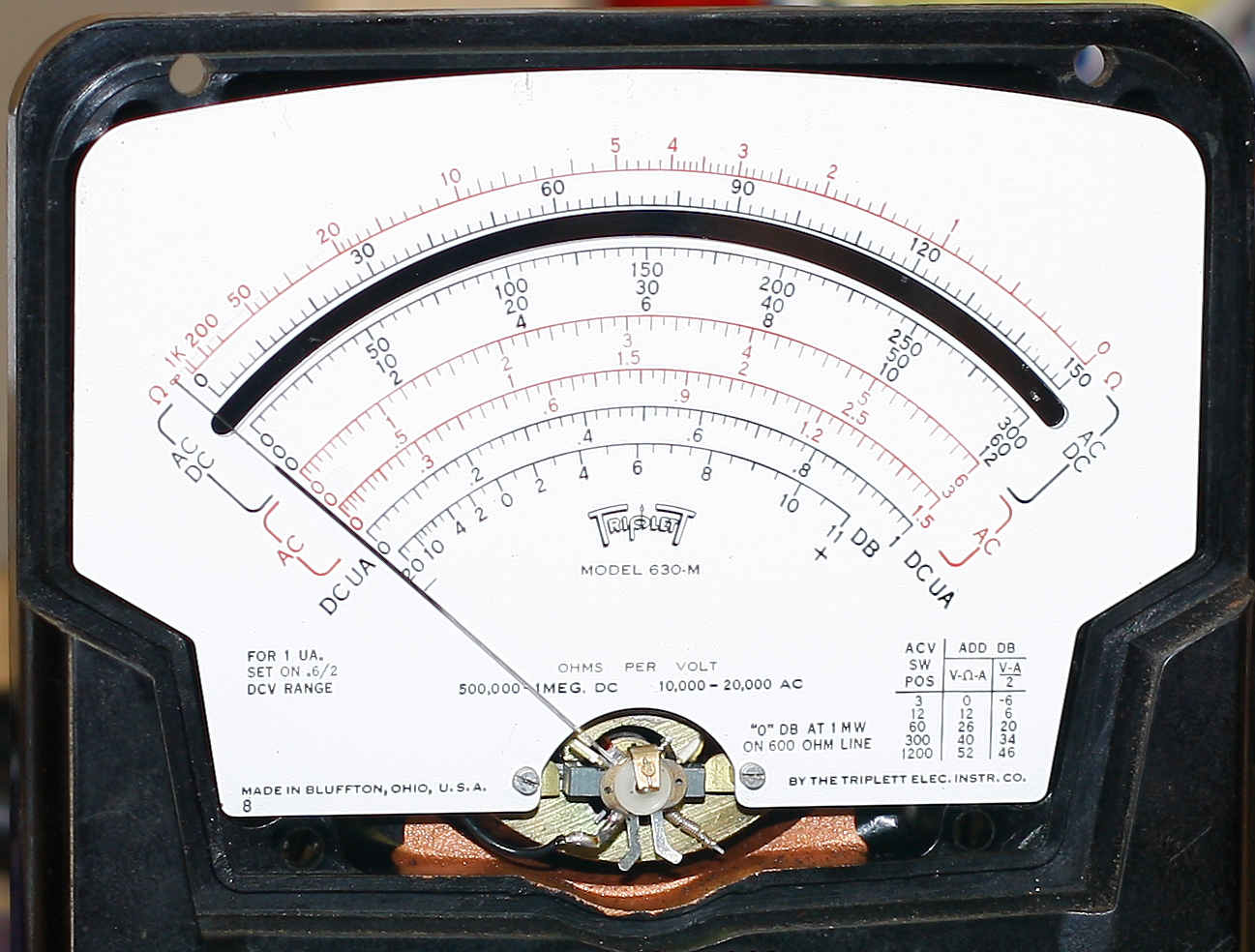
This meter uses a 1µA meter movement. According to Fred Scoles over on AntiqueRadioForum, the high sensitivity meant that they couldn't use the bakelite turret because it attracted too much static, and thus they went with a special PC board instead.
.
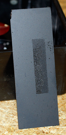
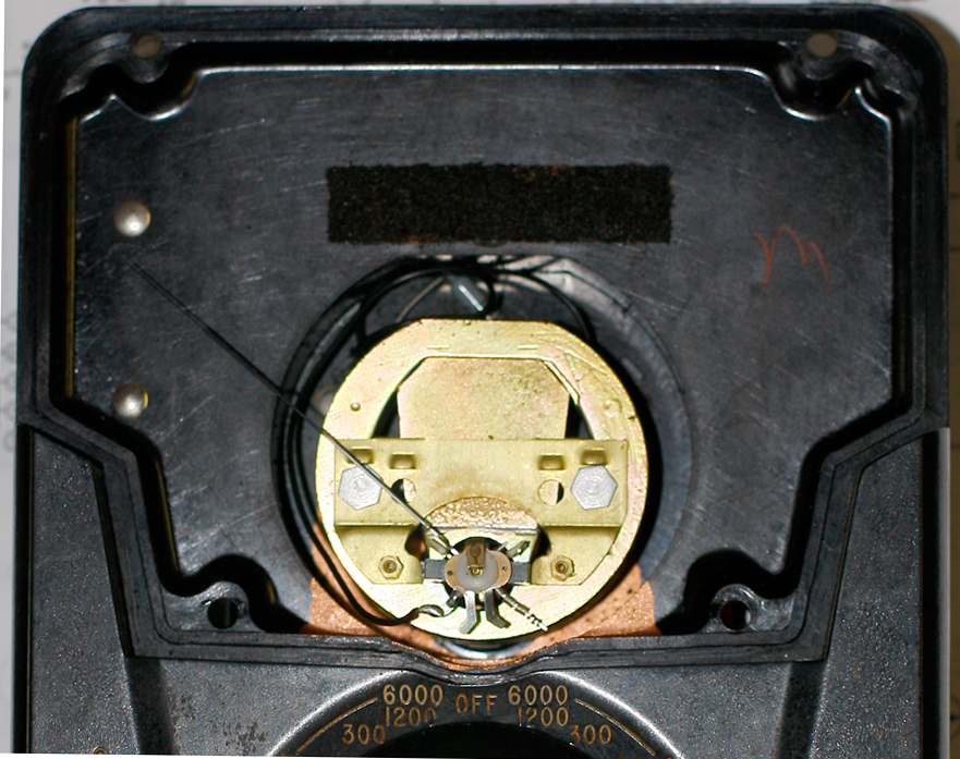 The lucite "glass" cover and meter face card have been removed, so you're looking at the meter movement. I blew out the debris with a hand-blower (a rubber bulb with a nozzle)—the kind I use to clean the sensor on my digital camera.
That black fuzzy stripe over the movement is what's left of a foam pad; that's what turned to dust and began to pollute the meter housing. This side of the foam pad was backed with glue and peeled off easily.
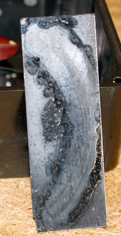
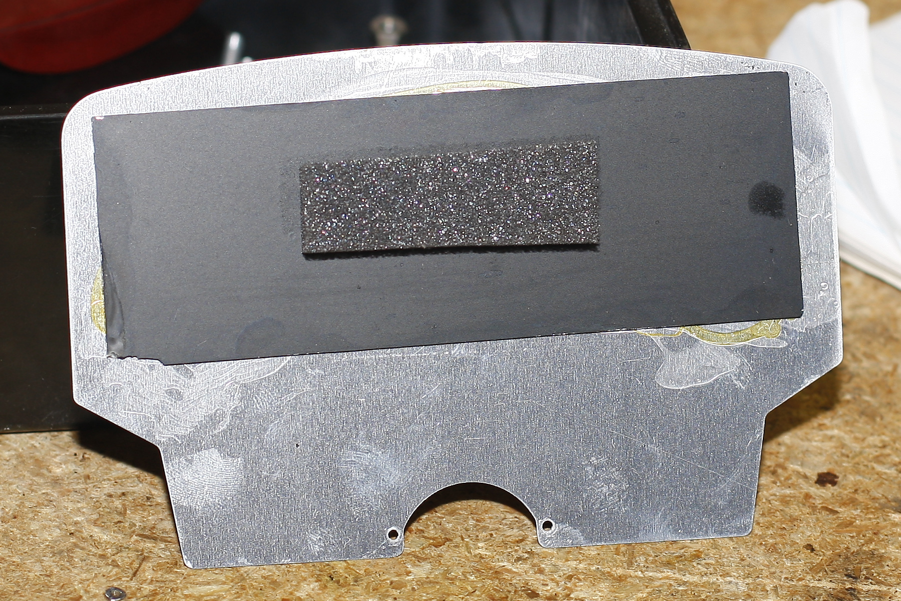
This is the mirror front and back before I cleaned it. The mirror is very thin. The black fuzzy stripe on the back is the where the foam pad rested. That little bit just wiped off easily.
The front of the mirror was affixed to the back of the face card with contact cement. Most of that came right off and the rest came off with a little alcohol. I cleaned the mirror with alcohol and window cleaner.
Here's the back of the face card with the mirror reattached (contact cement) and a bit of new anti-static foam. I took the foam from an IC that was using it as a rest.
 Face card/mirror/foam are cleaned up and back in place.
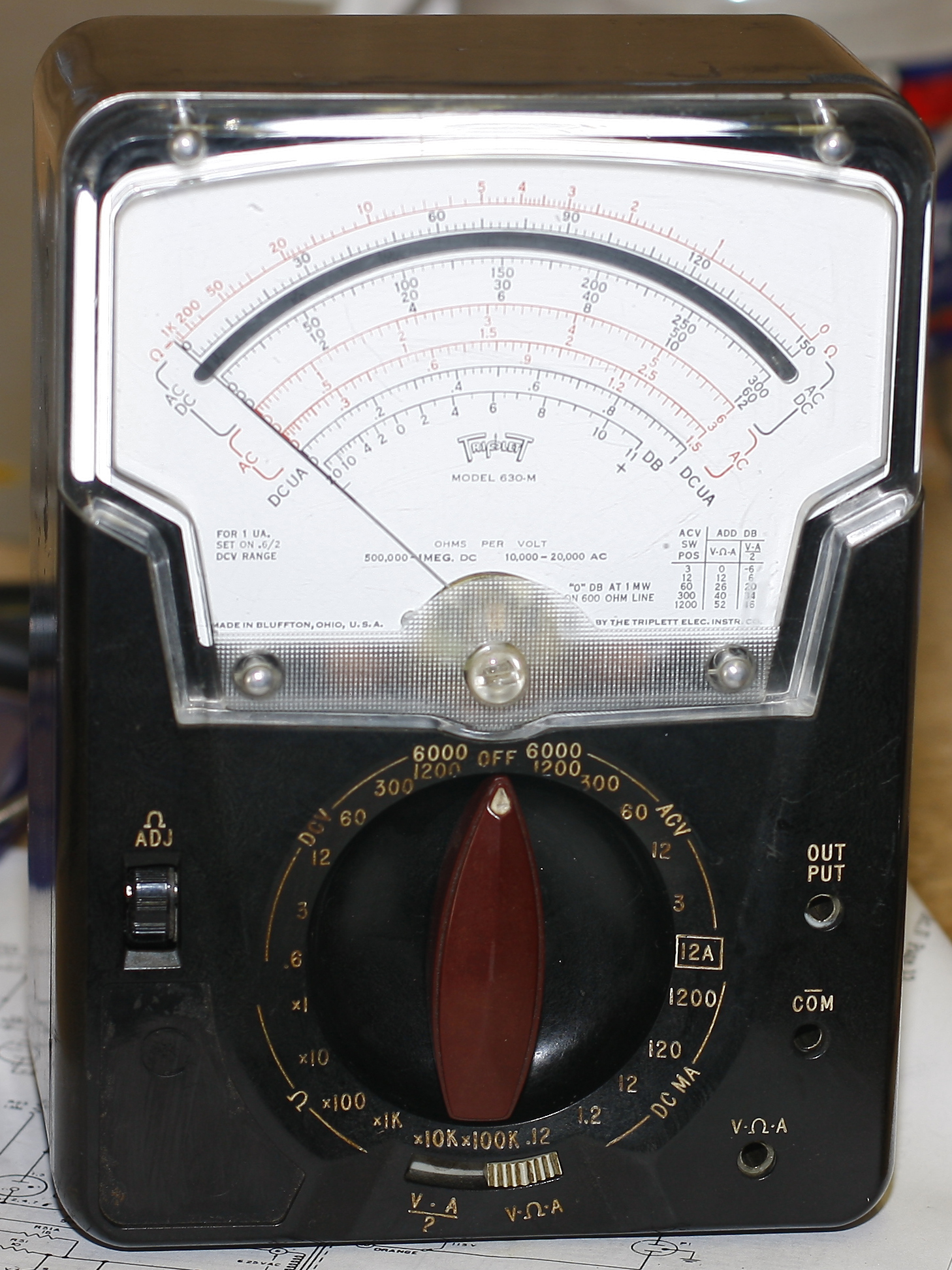
Reassembled and ready to go. The lucite glass cover cleaned up nicely using a little Meguiar's Plast-X, which is normally used to buff the haze off headlights. I've used it on various meter glasses and they nearly always look better (none look worse). It won't do miracles but I am pleased with how well it works. I then wiped it lightly with an anti-static dryer cloth (e.g. Bounce).
The meter works on AC volts and ohms; DC volts is dead. I didn't check current. So at some point I'll have to pull it apart again and see if I can find out what's wrong with the DCV section. But in the meantime, it's on the shelf and I'm admiring it.
 Triplett 2405 VOM
FYI: I no longer have this in my collection.
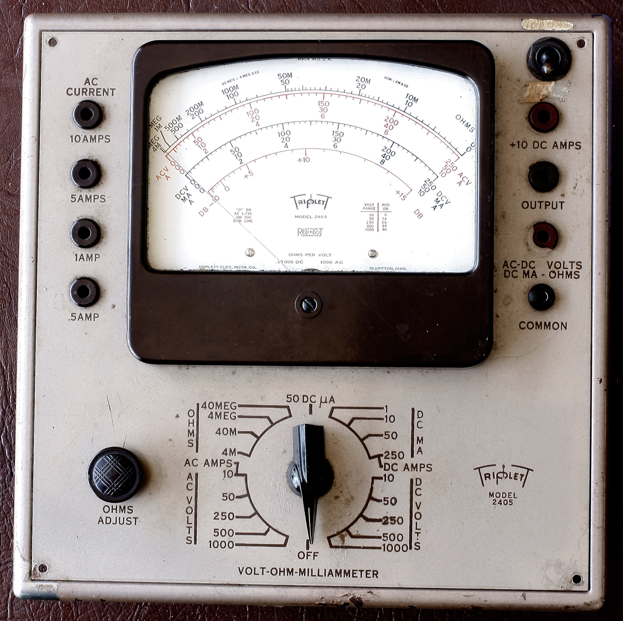
Here's something you don't see every day. This VOM antedates the famous 630 series (above); it's from 1947. At first glance (and a few more, as you look for the power cord) it appears to be a VTVM. It's big (10-inches square by 6-inches deep) and it has a sheet-metal case with a hinged cover.
This isn't a real "tear-down" per se, but I opened it up so here's what you get. As usual, click on a photo to get a larger size.
Front panel: this is before I cleaned it (though I couldn't do a lot with it; I was able to get some of the gunk off the right side). Nice, big display—you don't need trifocals to see that.
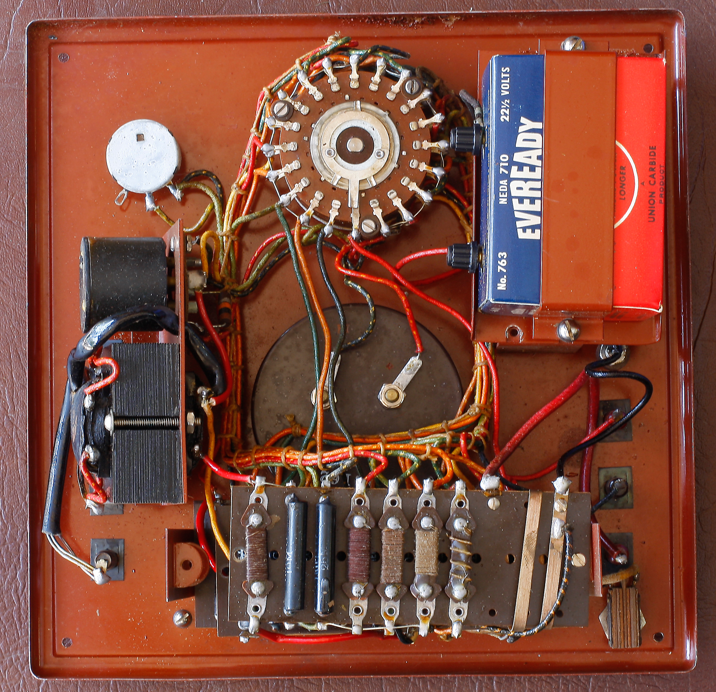
Here's the flip side of the front panel, albiet upside-down (the range switch is on top here, but it's really on the bottom). Triplett does some nice assembly work.
The battery here is an Everready 763, 22-½ volts. Can't get them anymore. When I had this out I saw someone wrote the date on it (1979). My DMM rates it at 22.5V, but I don't know what it'll really do under load.
Underneath that (invisible here) is a standard "D" cell. When it arrived, the D battery was split down the middle and acid was oozing out like cotton puffs. Luckily only the clip ends were corroded and the acid didn't appear to get anywhere else. I do have some corroded, flaking paint debris in the case back so it's possible that's where the acid attacked.
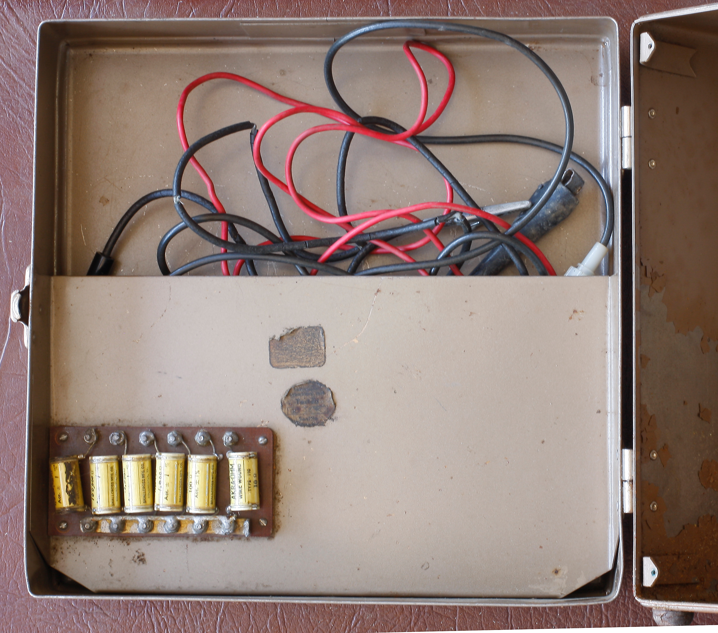 This is inside cover. There's a half-panel so you can tuck in the leads (mine are shot); on the front there's a series of 1% shunt resistors. Nice.
That's pretty much it.
Teardown Tuesday continues with more stuff being taken apart.