
The following article appeared in Radio Craft magazine, October and November 1938. PDF copies may be found at Americanradiohistory.com. A portion of the article is not available on their scanned copy, and I have not yet found another copy in order to restore it.
Signal-Test System of Trouble-Shooting
Laboratory test procedure and equipment have been speeded up and simplified to permit concentrating on a "dynamic" or operating test (of a faulty radio receiver) — including audible and visible analysis of the incoming signal (radio program or test-oscillator singal) and simultaneous test of operating voltages—from antenna posts to loudspeaker. Hitherto unattainable spot servicing results are secured.
John F. Rider
Service operations during recent years have shown the increasing need for a systematic method of trouble analysis or localization which would be applicable to all types of receivers—old, new, and yet to come. However, it has been virtually impossible to find what is the equivalent of a "common denominator" that would serve as a basis for such a trouble-shooting system. The writer feels that after 2 years of concentrated effort along theoretical and practical lines in a laboratory, such a basis has been found; Servicemen who have witnessed the application of the system concur in that opinion.
Servicing Procedures
During the process of selecting a basis for this sytem, every angle of receiver operation, all technical considerations relating to parts used in radio receivers, available testing equipment and actual service procedure were considered. The 3 existing methods of trouble localization, namely operating voltage measurement, resistance measurement, and probing by means of a signal generator, were given utmost consideration. While each was found to have its use and to be of value, none of the 3 were found suitable as a priamry or basic method of test. Of these 3, the Voltage Measurement test was found to be of greatest value as a supplimentary or secondary test, applicable after the trouble was localized; and this to be followed by the Resistance Measurement test still further for positive identification.
Voltage Measurement was found to be unsuited as a primary test because many types of troubles whic may exist in a radio receiver cannot be localized or analyzed with this type of test. This of course is not intended to in any way reduce the value of the voltage test a means of obtaining much needed information during the process of identifying the defective part.
Resistance Measurement, that is, the determination of the DC resistance of certain parts of the receiver, likewise fails as a basic, primary test because, as the experienced Serviceman well knows, many defects may exist in the modern receiver without manifesting any effect upon the DC resistance of the circuit. Furthermore, the fact that the receiver must in an inoperative state (that is, with the ON-OFF switch in the "OFF" position) when the test is made, still further reduces the efficacy of the system because very many defects in a receiver can be identified only when the receiver is in operation!
The Signal Generator Method of probing has been of value in the past but has lost a great deal of its effectiveness in the modern, complicated receiver because a number of sections in the receiver cannot be checked by means of the signal generator—at least not consistent with speed of operation. Judging by the trend of receiver design, the signal generator as a rapid probe will become less and less effective as time passes.
In view of these limitations, it is easy to see that none of these 3 systems constitutes a good, primary basis upon which a systematic method of trouble localization can be founded—particularly so when such a system must fulfill the following 3 requisistes:
- Universal Appication;
- Positive Identification, and;
- Speed of Operation.
Because of the very wide variety of receivers in use—that is, simple receivers years old, more recent receivers of complicated design, and the very modern receivers with their numerous interlocked circuits—the servicing test procedure must be one that is virtually independent of receiver design; if this can be achieved, the test method can be assumed to be independent of even the complicated receivers to come.
Such a system, founded upon a single item which constitutes a COMMON DENOMINATOR for all receivers, now is available.
Why "Signal Test" Servicing?
A Serviceman is called to repair a radio receiver for a definite reason. This reason, expressed in the simplest manner, is that the "signal" (radio program) listened-to by the customer in the form of music or speech is not satisfactory.
Irrespective of what may be the age of the receiver, or how complicated its wiring, or whether it has 1 tube or 50, the same thing is true . . . the customer does not know what is wrong with the receiver and, for that matter, neither does the Serviceman when he is first called, but one thing is certain—something has happened to the signal.
if the receiver has lost its sensitivity, the strength of the signal has suffered; why the receiver has lost its sensitivity is another question, but at the present time we are concerned with the signal only . . . If some condition in the receiver causes distortion, it manifests itself upon the signal . . . If for some reason the hum in the receiver becomes excessive, it has its effect upon the signal . . . If the receiver is inoperative, there is of course an absesne of signal.
[The following three paragraphs are illegible]
As you can see, the reference to the signal in the receiver and the voltages present in the receiver indicate that the system is of the dynamic vareity, that is, the receiver is placed in an operative state. By operative state, we do not necessarily mean correct signal transfer, because that may be the defect . . . what we mean is that the receiver is at least connected to the main power supply source; and, if possible, whatever voltages are available are being distributed to the various portions of the receiver.
"Signal Test" Requirements
In order to apply such a method of trouble localization effectively, 5 requirements must be fulfilled, as follows:
- It must be possible to trace the passage of a signal fed into the receiver through the various circuits of the receiver in the various forms the signal may take, as for example,
- oscillator frequency,
- radio frequency,
- Intermediate frequency and
- audio frequency, thus embracing all of the signal circuits between the antenna and the speaker.
- It must be possible to trace the signal through the receiver without so altering the constants of the circuit during the test as to impare the operation of the receiver, thus nullifying the observations.
- The voltage tests must be of such variety as to embrace not only the operating voltages, but the control voltages developed by the signal.
- The method of voltage measurement must be such that it can be done simultaneously (if so desired) with the observation of the signal and at points common to the signal and the voltage as, for example, the control-grid of a demodulator tube or RF tube.
- The measurement of the DC voltages must be made with reasonable accuracy with respect to the true voltage present at the ponit tested without altering the constants of the circuit. This means that the voltage measurement method must be substatially free of circuit limitations.
 "Signal Test" Trouble-Shooting AVC Circuits
You can readily appreciate the value of such a system, if you will consider the following examples. These troubles are not particularly complicated but have nevertheless been quite difficult to localize heretofore.
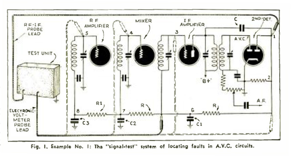
Supose, as the first example, that the trouble seems to be in the automatic volume control circuit . . . Suppose, further, that by means of a single probe you could check the presence or absence of the IF signal at the anode of the AVC tube, point 1 in Fig. 1 (or at the control-grid, if the AVC tube happened to be of the same type); and simultaneously measure the rectified voltage being developed by the AVC rectifier, point 2 in Fig 1 (this rectified voltage being the true voltage within a few percent). The information thus gleaned is definite and is obtained in the amount of time required to place 2 probe points in contact with the circuts under observation. Assuming that voltage is available at the AVC tube, the voltage probe then is placed upon the control-grids of the various control tubes (one tube at a time) and the AVC voltage applied to that grid (if it is being applied) is measured. See points 3, 4, and 5 in Fig 1.
There is a very defnite convenience provided by such ease of operation because there never can be any doubt either (1) about the presence of a signal (the program for instnace) at any point in the signal circuit, or (2) about the voltage (power-supply output) at the point. And if the voltage is developed as a result of the application of the signal, then it is of great importance to be able to establish both simultaneously, so as to obtain positive identification of conditions at the point being tested. (The high resistances in the circuit do not interfere with voltage measurements.)
AFC Circuits
After all is said and done, servicing is a problem when the "difficult-to-find" troubles exist in a receiver and it is then that a system which localizes rapidly proves itself. Take, for example, a condition such as this.
 The automatic frequency control circuit in a receiver is not functioning due to a defect in the "discriminator" system. Existing systems of trouble analysis would find it extremely difficult to check the signal and control voltages present in such a circuit.
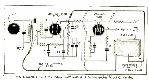
But with the signal as the basis of trouble analysis, and the proper method of voltage measurement as the secondary test, it would be possible to establish simultaneously the presence of the signal voltages being fed into the discriminator transformer and the discriminator diodes as well as the control voltages developed in the output of the diode.
The signal voltages are checked by placing the probe point in contact with the signal-carrying circuits any place along the line, points 1, 2, 3 and 4, in Fig. 2. Although present-day voltage measurement, if applied to such a circuit, would indicate the presence or absence of control voltage output, it would in no way imbrace the remainder of the circuit. If no voltage were available, the conditions in the remainder of the circuit would remain a mystery. The signal generator method of probing would not operate because too many independent, yet assocated, elements remain in the circuit and cannot be isolated. But with the signal-tracing method, the signal fed into the discriminator transformer can be checked across each and every part of the transformer assembly.
Imperfect-Filtering Conditions
Still antoher example of interest and one which is representative of an uncommon trouble is imperfect filtering between associated circuits carrying currents of different frequencies. the signal-tracing method, in contrast to other test systems, allows probing of the various circuits at the different frequencies to establish if the improper operation of the receiver is due to the fact that filter circuits are not intact. Such probing is done by placing aprobe in cotnact with the various elements along the circuit which connects the 2 portions of the receiver as, for exaple, the IF circuit and the RF via the AVC system. See points 6, 7 and 8 in Fig. 1. The various feed circuits associated with the AVC system are checked to see if an intermediate frequency is feeding into the RF or mixer input circuit, because one of the bypass condensers or isolating resistors in the AVC bus is not intact.
Shadowgraph Circuits
The number of hitherto complex troubles which can be easily detected by means of signal tracing is entirely too great to quote in these pages; however, before closing this article, we would like to give just one more specific case, and you will no doubt see the value of knowing whehter or not a signal exists at certain points in a receiver. 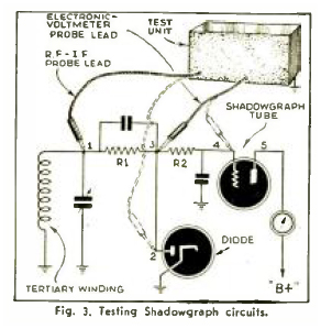 The Shadowgraph circuit in Philco receivers receives its voltage from a diode rectifier, which in turn receives its signal voltage from the tertiary (third) winding in the last IF transformer. The diode load is 2 MΩ and the shadowgraph tube grid resistor is also 2 MΩ. The rectified voltage fed to the shadowgraph tube through the 2 MΩ resistor is very low. If the shadowgraph is inoperative and present-day routine tests are applied, a number of tests, at least 6, would be needed to establish that the tertiary winding feeding this tube is not feeding a signal to the diode rectifier.
With the trouble localization method outlined herein and fulfilling the requirements set forth, on the other hand, a single operation would establish this condition and 2 measurements instead of 6 would indicate that the diode was not supplying the bias voltage. The entire circuit could be checked in less than 1 minute to establish complete conditions at the various points in the system. Sig Fig. 3.
As you no doubt realize, the application of the system to daily, run-of-the-mill servicing is dependent upon operating and control voltage measurements of a type and with a meter hitherto not available. Such a voltmeter would be used to check the DC voltages at the control-grids; and the bias voltage applied through the 2 MΩ resistor to the shadowgrph tube control grid. This voltmeter would also indicate DC voltage of either plus or minus polarity with respect to ground. with it could be plotted the AFC voltage developed by the discriminator tube as the receiver was tuned both sides of the carrier, by simply connecting the voltmeter probe to the control voltage bus . . . So much for these peculiar troubles.
ETC—Including "Intermittents"
Items such as shorted bypass condensers, open tuning coils, shorted transformers of various kinds, open-circuited or shorted resistors which influence both signal and voltage, are located with the greatest of ease and do not justify extended discussion.
Last but by far not the least is the advantage of such a method of testing when applied to "intermittents." After a prolonged series of tests we feel confident in saying that such a system, when properly applied, is the solution to the "intermittent" problem (unexpected cutting off of reproduction). This has been proved in practice upon a number of receivers. As you read the following description of the method used to trace the signal and note the breakdown of the receiver into various sections, you will see how the "intermittent" situation is solved.
"Signal-Test" Equipment
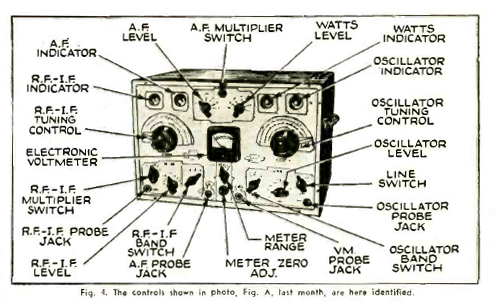
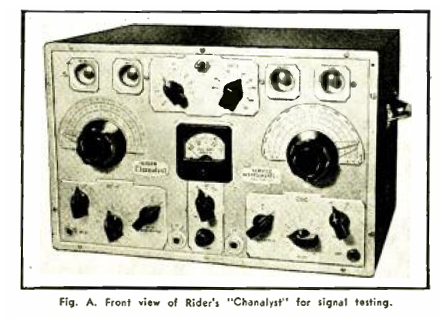 In order to be able to most quickly and conveniently apply this common-denominator method of trouble localization in special test equipment developed by the writer. It is shown photographically in Figs. A and B. This unit used embraces a number of "pick-up channels," each of these channels being calibrated in reference units and connected to an indicator—actually, a cathod-ray-tube tuning eye.
One pick-up or test channel covers the RF and IF range from 95 kc to 1,700 kc in 3 bands.
Another channel covers the oscillator stage in a superheterodyne and is calibrated over a range from 600 kc to 15,000 kc (15mc) and a supplimentary arrangement provides a check upon the performance of the oscillator up to 70 mc.
Another channel operates over the audio-frequency band of 50 to 50,000 cycles.
A 4th channel is used as a watts power or "wattage" indicator to show the current consumption of the receiver under test.
And 5th, an electronic voltmeter of special design is used. it has an input resistance value of 10 MΩ and is operatives over 4 ranges. these are -5 through 0 to +5 volts, -25 volts through 0 to +25 volts; -100 volts through 0 to +100 volts and from -500 through 0 to +500 volts—without switching th eprods to compensate a polarity change!
Naturally you wonder how the signal is traced without interfering with the normal operation of the receiver. The RF, IF and oscillator channel pick-up is accomplished through a coupling capacity of less than 1.0 µµF (one micro-microFarad). This minute coupling capacity is located in the probe, which is connected to the unit through shielded cables. Since testing of RF channels is done at broadcast frequencies between 600 and 900 kc, the detuning effect is negligible.
This entire RF and IF band is calibrated in freuqency. Checking of the RF channels at frequencies aboe the broadcast band is not provided because monitoring of the other portions of the receiver at frequencies above the broadcast band immediately identifies if the RF circuit is inoperative. In other words, if a 3-band receiver operates over the broadcast band and the next band, but is inoperative over the highest band, the trouble is immedately localized as being in the RF system, because the IF channel in the receiver is not changed and because the oscillator pick-up channel or the voltmeter is used to check the operation of the oscillator.
The detuning effect upon the oscillator at the test frequencies used in the broadcast band is negligible. At the higher frequencies the detuning is mroe apparent, but it does not interfere with the operation of the unit for any type of test, because the sole purpose of the pick-up channel is to see if the oscillator is operating and to probe through the oscillator circuit in the receiver to see if the circuit is intact.
A pick-up probe is provided for the RF and IF channel, the oscillator channel; the AF channel and the voltmeter. As the result of the design of the unit, each or all of these probes can be used at the same time and placed in contact with any portion of the respective circuits in the receiver.
RF-IF Channel (Continued)
 The RF-IF channel is resonated to the frequency of the RF or the IF circuit and it is possible to check the presence or absence of these signals, the level of the signal, and its character. The latter can be fed to a pair of headphones or to an oscilloscope if so desired. The indicator connected to this and the oscillator and AF channels operates upon the rectified signal picked up in these channels. In the case of the RF-IF channel, the rectified signal can be fed to earphones for aural observation; or to an oscilloscope for visual observation. The pick-up channel is free from distoration, hence a signal aurally or visually observed has the chracter of the signal (that is, whether it is intermittent, clear, mushy, with strong hum, etc.) at the point in the receiver 9where RF or IF currents flow) where the probe is placed.
The output of the AF chnnel, unrectified, can be fed to earphones or to an oscilloscope for visual observation. As in the case of the previous channels, the level as well as the character of the signal can be established. Like the other channels, the AF signal can be picked up any place in the AF system. Thus it is possbile to check fro the output of phase inverter tubes to see that the input to the output push-pull tubes is equal. the same applies to voltages across the sections of push-pull transformers. etc.
The design of the voltmeter is such that it can be connected anywhere in the receiver circuit and it will indicate the proper polarity of the circuit without switching leads. Also, it can be connected to any point in the tuned circuits where a DC voltage exists without interfering with the signal of the circuit. For example, it can be connected to the control-grid of the RF mixer, or IF tubes to indcate the AVC voltage, and as the receiver is tuned or the test oscillator varied so as to vary the signal passing trhough the receiver, and so the AVC voltage, the mter will indicate the simulatenous variation in AVC Voltage at the control-grid of the tube being checked.
The "Wattage" Indicator
The "wattage" (watts power) indicator channel is an important part of the system because, when used in conjunction with a test of the highest DC voltage in the receiver, as for example the voltage upon the plate or screen-grid of the output tube, it will immediately indicate the tube of trobule in the event of a condtion which loads the power supply, thereby increasing the watts consumption of the receiver. This "wattage" indicator is calibrated from 25 to 250 watts and is automatically brought into the circuit when the receiver is placed on test. Any abnormal or subnormal watts indication when combined with the DC voltage available from the power suply, immediately supplies definite information relative to the type of trouble in the receiver and whether or not a further test is possible.
Space does not perfmit of a resume of what can be done with a system of trouble localization of this type, but if you appreciate the significance of being able to check the signal in any point in the receiver, you will readily realize the ease in which a defect can be located. In all cases where a test is possible, a signal is fed into the antenna circuit from any inexpensive test oscillator. if the receiver is "dead" the signal is traced to the poitn where it "dies" in the receiver. If the sensitivity is low, the signal is checked from stage to stage, from winding to winding, and observation made of the increase in signal strength as progress is made through he receiver. Simultaneously with these signal tests are made voltage tests in any place that is suspected; none of these voltage tests impair the operation of the receiver.
Circuit Identification
Details which will make it more conveninet to identify the various circuits of the complete schematic circuit of the Chanalyzer follow. This digram fulfills the requirments of (1) Universal Application; (2) Positive Identification; and (3) Speed of Operation, as required in order to make the new test procedure practicable.
(Unless otherwise specified, asll the resistors shown in the digram, Fig. 5, are 1/2-watt units; and the condensers, 500 V in mica, 400 V in tubular, and 450 V DC in dry-electrolytic types. Note that all other available information apperas in the diagram or its caption.)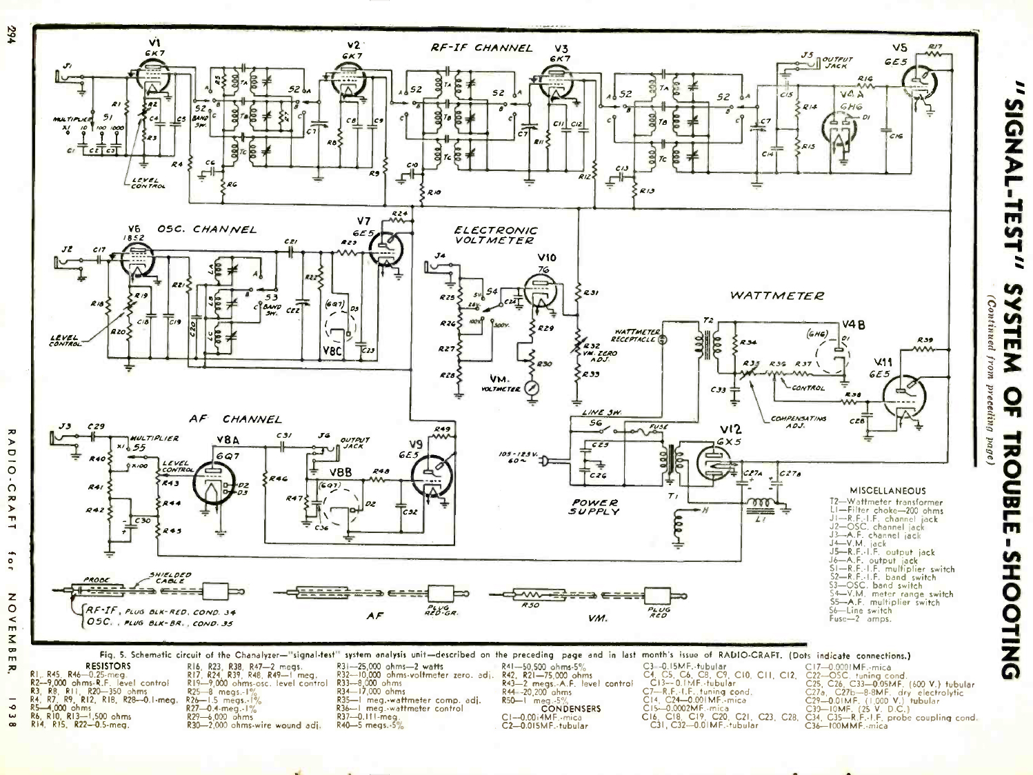
Radio and Intermediate-Frequency Channel
V1 to V5 — Five tubes are employed in the RF-IF channel; 3 as high-gain tuned amplifiers, the 4th as a diode rectifier, and the 5th as an electron-ray indicator.
The amplifier covers 3 frequency bands; 600 kc to 1,700 kc; 240 kc to 630 kc, and 95kc to 260 kc., the amplification being substantially flat over each band. The input-circuit is calibrated, thereby making the channel suitable for gain measurements.
A jack in the indicator circuit permits the output of the amplifier to be fed to headphones or an oscilloscope so that the signal can be heard or its waveform examined. The rectifier circuit is so designed that the output depends upon the the carrier voltage and not the modulation component; therefore the indication does not depend on the percentage of modulation of the input signal.
Oscillator Channel
V6 to V8C — The oscillator channel employs 3 tubes; a tuned amplifier, a diode rectifier and the electron-ray indicator.
Coverage of oscillator operation extends as high as 70 megacycles. The tuned amplifier used in the channel operates over 3 frequency bands; 600 kc to 1,700 kc, 1,650 kc to 4,900 kc, and from 4,800 kc to 15,000 kc. Pick-up to the circuit is through a sheilded cable which terminates in a capacity of less than 1 µµF. The input circuit is equipped with a gain control.
In order to provide for maximum sensitivity when working with modern superhetrodyne receivers with comparatively low oscillator output voltage, high gain is obtained in the oscillator channel by using a type 1852 tube as the amplifier.
The oscillator channel is used when checking oscillator operation over the 600 kc to 15,000 kc range. When checking for operation of oscillator systems without regard to frequency of the output, the electronic volt-meter channel is used.
AF Channel
V8A to V9 — The AF channel employes 3 tubes; an amplifier, a diode rectifier and an electron-ray indicator.
It is resistance-capacity coupled and "flat" over a frequency range of 50 to 50,000 cycles. The sensitivity of the amplifier is 0.1-volt for full indication and is operative over an input voltage range from 0.1-volt to 1,000 volts. A jack is provided in the output circuit of the amplifier so that the signal output can be fed to headphones or to an oscilloscope for aural or visual observation. The continuously variable attenuator and a switch-controlled, single-step attenuator provide attenuation over a ratio of about 10,000 to 1.
Electronic Voltmeter
V10 — This voltmeter employes a tube and a meter-type indicator.
The meter has a center zero and indicates both positive and negative voltages with respect to ground. The range of voltages covered by the meter is as follows: -5 to 0 to +5; -25 to 0 to +25; -100 to 0 to +100; and -500 to 0 to +500. The input resistance of the instrument on all scales is 10 MΩ, which means that on the low-voltage scale, the resistance is equal to 2 MΩ/volt. All DC operating and control voltages may be measured with the instrument, thus making it possible to measure RF, IF, AF and oscillator voltages directly at the grid and plate without interfering with the operation of the receiver.
Watts Indicator
V4B & V11 — The watts indicator employs 2 tubes: a diode rectifier and an electron-ray indicator.
It is calibrated to indicate the power consumption of the receiver under test and covers a range from 25 to 250 watts. This unit is automatically connected into the circuit when the receiver is plugged into the receptacle provided for that purpose. To obtain the amount of power consumed, the watts-level pointer is turned until the shadow in the watts indicator is a minimum, the eye is just closed. The power in watts then is read directly fro the scale engraved on the panel.
Power Supply
V12 — The power supply employs a full-wave rectifier and functions as the source of the operating voltage for all the tubes in the Chanalyst. Exceptional care has been taken in the design of the filter so that the hum level is extremely low.
The Cables and Probes
Four probe leads are furnished. The cables have low capacity, are shielded, and have an outer covering of braid. The probe handles contain the coupling capacity for the RF-IF and oscillator channels. Four small copper clips, having internally-threaded sleeves, can be screwed over the prods when a permanent connection is required as in servicing intermittent receivers. Two additional flexible connectors which can be screwed over the prod so as to enable connection to the tube sockets from the top with the tubes in place are also provided.
It might be of interest in closing to say that this method of operation makes possible, in about 50 percent of the service calls, a very thorough inspection of a receiver in the customer's home without even pulling the chassis from the cabinet, working right from the top of the chassis. As a matter of fact, it is possible to approximate the defect and thus render an approximate estimate without gambling with the time required to "pull" the chassis (take it to the shop) and render the estimate, only to be told that it is too high and, hence, lose the job.
This article has been prepared from data applied by courtesy of Service Instruments, Inc.