I don't know if anyone else will care, but I like it.
I own a lot of light meters. Most are them are selenium jobs which do not require batteries, but the ones from the 60s and 70s used CdS cells and ran off 1.35v mercury batteries. Some of my cameras from that era take them as well.
The major problem is that mercury batteries are no longer legal to manufacture or sell in the USA, which means a lot of my equipment is battery-less. There are a variety of solutions:
I usually don't want to go to all that hassle—I just want to know if the meter or camera works. I've also got a few foreign meters which take oddball batteries and nobody quite knows what voltage they're supposed to be. That's no good.
I wanted a small power supply, something I could clip onto my meter (or camera) battery posts and see if it works. So I put this project to my father, who's a retired electronics tech and knows how to do these things.
We ended up with a simple circuit. It takes a 9v battery so I can run anything up to 9v. It's designed around two LM319T voltage comparators, purchased at Radio Shack (I know, but it was a weekend project), each one it its own circuit. There are two switches, and ON-OFF and a voltage switch. One side of the switch runs through a comparator that's pegged for 1.35v output, and the other goes to a comparator attached to a variable resistor which allows you to set the output voltage between 0 and 9v.
For the variable side, you hook it up to a voltmeter and turn the knob until you dial in the voltage you want, then hook it up to your meter or camera.
You can also do some reverse engineering with it. I have a Russian light meter which took an oddball battery and I didn't know the voltage. So I hooked up this power supply to it, and turned the voltage knob until the light meter gave me the proper reading (I compared it against a trustworthy meter). Then I used my voltmeter to see what voltage I was producing.
The schematic and parts lists follow. Sorry about the quality as I'm not good at drawing in Photoshop--but it's a little better than the hand-drawn original. There's nothing exotic here—you should be able to get the parts from Radio Shack or a decent electronics shop.
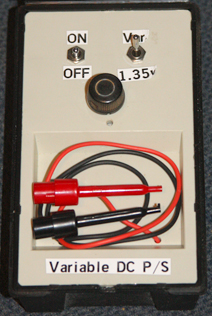 Here's the front panel. On/OFF is the switch on the left, the voltage range output is on the right. When the switch is UP you get a variable voltage as controlled by the knob in the center. When it's down, you get 1.35v and the knob has no effect. Clip leads to connect to the battery terminals in the meter or camera are at the bottom. Here's the front panel. On/OFF is the switch on the left, the voltage range output is on the right. When the switch is UP you get a variable voltage as controlled by the knob in the center. When it's down, you get 1.35v and the knob has no effect. Clip leads to connect to the battery terminals in the meter or camera are at the bottom. |
The battery is tacked onto the panel with rubber cement. |
New content ©opyright by James Ollinger. All rights reserved.
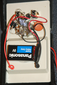 Same thing but the front panel has been flipped over. There's no PC board--the case of the variable resistor serves as ground for everything, and the components are soldered together.